Section 7.3 Point Contact between Two Rigid Bodies

Joints resulting from point contact between two surfaces play a special role in countless mechanisms, such as ball bearings, gears, cams, etc.

Subsection 7.3.1 Assumptions

Consider two rigid bodies \(\cB_{1} (O_1 , \bx_1 , \by_1 , \bz_1)\) and \(\cB_{2} (O_2 , \bx_2 , \by_2 , \bz_2)\) in relative motion and maintained in contact at a point \(I\text{.}\) Assume that at least one of the surfaces is smooth.  1  At any given time, there exists a point instantaneously attached to \(\cB_1\) which coincides at \(I\) with a point instantaneously attached to \(\cB_2\text{.}\) Assume that there exists a tangent plane \(\Pi\) to the surfaces bounding \(\cB_{1}\) and \(\cB_{2}\) at point \(I\text{.}\) We denote by \((\btau_1, \btau_2, \bn_{12})\) a basis of unit vectors, with \(\bn_{12}\) the unit normal vector to \(\Pi\) pointing from \(\cB_{1}\) to \(\cB_{2}\text{.}\) Vectors \((\btau_1, \btau_2)\) lie in the tangent plane \(\Pi\text{.}\) See Figure 7.3.1.
Of interest is the motion of \(\cB_2\) relative to \(\cB_{1}\text{.}\) The parametrization of the position of both \(\cB_1\) and \(\cB_2\) is typically defined relative to a referential \(\cB_0\) (relative to which the motions of \(\cB_1\) and \(\cB_2\) are observed). In this case, the kinematics of \(\cB_2\) relative to \(\cB_{1}\) can be related to the kinematics of \(\cB_2\) and \(\cB_{1}\) relative to \(\cB_0\) by application of formula (6.5.4):
\begin{equation} \{ {\cal V} _{2/1} \} = \left\{ \begin{array}{c} \bom_{2/1} \\ \vel_{I \in 2 / 1} \end{array} \right\} = \{ {\cal V} _{2/0 } \} - \{ {\cal V} _{1/0 } \} = \left\{ \begin{array}{c} \bom_{2 / 0} - \bom_{1 / 0}\\ \vel_{I \in 2 / 0} - \vel_{I \in 1 / 0} \end{array} \right\}\tag{7.3.1} \end{equation}
We now describe the physical characterization and properties of the two kinematic quantities \(\vel_{I \in 2 / 1}\) and \(\bom_{2 / 1}\text{.}\)
Figure 7.3.1. Two rigid bodies in contact at a point \(I\)

Subsection 7.3.2 The slip velocity of a rigid body

Definition 7.3.2. Slip Velocity.

The slip velocity of body \(\cB_2\) relative to body \(\cB_1\) at contact point \(I\) is the instantaneous velocity \(\vel_{I \in 2 / 1 }\) of contact point \(I\text{.}\) It characterizes the slipping (or sliding) motion of \(\cB_{2}\) relative to \(\cB_{1}\text{.}\)
For the contact to be maintained, the slip-velocity must remain in tangential plane \(\Pi\text{,}\) that is, the component of \(\vel_{I \in 2 / 1}\) along unit vector \(\bn_{12}\) must be imposed to zero
\begin{equation} \vel_{I \in 2 / 1 } \cdot \bn_{12} = \vel_{O_2 \in 2 / 1 } \cdot \bn_{12} + \bom_{2 / 1} \cdot (\br_{O_2 I} \times \bn_{12} ) = 0\tag{7.3.2} \end{equation}
This provides an equation of the type
\begin{equation*} f_1 (\bq) \dq_1 +f_2 (\bq) \dq_2 + \cdots + f_6 (\bq) \dq_6 = 0 \end{equation*}
where \(\bq = (q_1 , \ldots, q_6)\) represents the six coordinates which define the position of \(\cB_2\) relative to \(\cB_1\text{.}\) Hence the contact of \(\cB_2\) with \(\cB_1\) at point \(I\) reduces the mobility of \(\cB_2\) relative to \(\cB_1\) from six to five. In general, this equation is expected to be integrable and to provide a geometric constraint of the type (7.1.1).
Often the parametrization of the position \(\cB_1\) relative to \(\cB_2\) implicitly takes into account the contact at \(I\text{.}\) In this case, condition (7.3.2) will be automatically satisfied. In other cases, equation (7.3.2) provides a simple way to impose this geometric condition, once the slip-velocity at \(I\) has been found. See Subsection 7.3.5 for examples.
There exist two practical ways to determine the slip-velocity at \(I\text{:}\)
  1. It can be related to the motion of point \(I\) relative to \(\cB_{1}\) and \(\cB_{2}\) by application of formula (6.2.1):
    \begin{equation} \vel_{I \in 2 / 1 }= \vel_{I / 1 } - \vel_{I / 2 }\tag{7.3.3} \end{equation}
    where
    \begin{equation*} \vel_{I / 1 } = \left( {d\br_{O_1 I} \over dt} \right)_1, \qquad \vel_{I / 2 } = \left( {d\br_{O_2 I} \over dt} \right)_2 \end{equation*}
    As \(\cB_2\) moves relative to \(\cB_1\text{,}\) contact point \(I\) describes the trajectory \(\cC_1\) relative to \(\cB_1\) inscribed on the surface of \(\cB_1\) and the trajectory \(\cC_2\) relative to \(\cB_2\) inscribed on the surface of \(\cB_2\text{.}\) Velocity \(\vel_{I /1}\) is tangent to curve \(\cC_1\text{,}\) while velocity \(\vel_{I /2}\) is tangent to curve \(\cC_2\text{.}\) Since both vectors \(\vel_{I /1}\) and \(\vel_{I /2}\) must necessarily lie in plane \(\Pi\text{,}\) a consequence of equation (7.3.3) is that the slip velocity also lies in tangential plane \(\Pi\text{,}\) as long as contact is maintained. This provides a justification of condition \(\vel_{I \in 2 / 1 } \cdot \bn_{12} = 0\) of equation (7.3.2).
  2. It can be related to the motion of \(\cB_{1}\) and \(\cB_{2}\) relative to a referential \(\cB_0\) according to equation (7.3.1):
    \begin{equation} \vel_{I \in 2 / 1} = \vel_{I \in 2 /0}- \vel_{I \in 1 /0}\tag{7.3.4} \end{equation}
    where
    \begin{equation*} \vel_{I \in i /0} = \vel_{O_i / 0} + \bom_{i / 0} \times \br_{O_i I}, \qquad i=1,2 \end{equation*}
    is the velocity relative to \(\cB_0\) of the point of body \(\cB_i\) coinciding with contact point \(I\text{.}\) Equation (7.3.4) is especially useful when the motions of \(\cB_{1}\) and \(\cB_{2}\) are parametrized relative to a referential \(\cB_0\text{.}\)
We now states the following definition.

Definition 7.3.3. No-Slip Condition.

The motion of \(\cB_{2}\) relative to \(\cB_{1}\) is said to be without slip at contact point \(I\) if the slip-velocity at \(I\) is identically zero during a finite time interval:
\begin{equation} \vel_{I \in 2 /1 } = {\bze} \tag{7.3.5} \end{equation}

Remark 7.3.4.

If \(\cB_2\) is in motion relative to \(\cB_1\) without slipping, then \(\cB_{2}\) is in instantaneous rotation relative to \(\cB_1\) about the axis \(\Delta_{2/1}\) passing through \(I\) and directed along angular velocity \(\bom_{2/1}\) (only as far as velocities are concerned). Hence, axis \(\Delta_{2/1}\) is the instantaneous axis of rotation of \(\cB_2\) relative to \(\cB_1\text{.}\)

Remark 7.3.5.

In general, the no-slip condition (7.3.5) will generate two non-holonomic, non-integrable constraint equations of the type (7.1.2). The mobility of \(\cB_2\) relative to \(\cB_{1}\) is then reduced to three.
\(\danger\)One must never determine the slip velocity \(\vel_{I \in 2 /1 }\) by direct time-differentiation of a position vector \(\br_{O_1 I}\) (relative to \(\cB_{1}\)). The same applies to velocities \(\vel_{I\in 2/0}\) and \(\vel_{I\in 1/0}\text{.}\)

Subsection 7.3.3 Pivoting and Rolling of a Rigid Body

By writing the angular velocity \(\bom_{2 /1}\) as the sum of tangential and normal components, we can characterize the motion of body \(\cB_{2}\) relative to body \(\cB_{1}\) in terms of its pivoting and rolling components.

Definition 7.3.6. Pivoting and Rolling.

At any instant, the angular velocity \(\bom_{2 /1}\) can be written as the sum of a normal component \(\bom^n _{2/1} \) normal and a tangential component \(\bom^t_{2/1}\) with respect to tangent plane \(\Pi\) at \(I\text{:}\)
\begin{equation} \bom^n_{2/1} = ( \bom _{2/1} \cdot \bn_{12} ) \bn_{12}, \qquad \bom^t_{2/1} = \bn_{12}\times ( \bom _{2/1} \times \bn_{12} )\tag{7.3.6} \end{equation}
The normal component \(\bom^n _{2/1}\) characterizes the pivoting motion of \(\cB_{2}\) on \(\cB_{1}\text{,}\) while tangential component \(\bom^t_{2/1}\) characterizes its rolling motion. If these two components are non-zero, body \(\cB_2\) is said to roll and pivot (with or without slipping) relative to body \(\cB_1\text{.}\)

Subsection 7.3.4 The Axodes of a Rigid Body Motion

We have learned in Chapter 5 that, in general, the kinematic screw \(\{ {\cal V} _{2 / 1 } \}\) is characterized at any given time by its instantaneous screw axis \(\Delta_{2/1}\) directed along \(\bom_{2/1}\) and passing through a point \(I\) whose position is given by
\begin{equation*} \br_{O_2 I} = {\bom_{2/1}\times\vel_{O_2 /1} \over \bom_{2/1}^2} \end{equation*}
as long as \(\bom_{2/1}\neq \bze\text{.}\)
Viewed by an observer attached to \(\cB_1\text{,}\) rigid body \(\cB_2\) is instantaneously in helical motion about \(\Delta_{2/1}\text{,}\) that is, its velocity field appears to be the sum of rotational velocity field about \(\Delta_{2/1}\) and a translational velocity field along \(\Delta_{2/1}\text{:}\) for any point \(P\in\cB_2\text{,}\) we have
\begin{equation} \vel_{P\in 2 / 1} = p_{2/1} \, \bom_{2/1} + \bom_{2/1}\times \br_{IP}\tag{7.3.7} \end{equation}
where the pitch} \(p_{2/1}\) is given by
\begin{equation*} p_{1/2} = {\bom_{2/1}\cdot\vel_{Q \in 2 /1} \over \bom_{2/1}^2} \end{equation*}
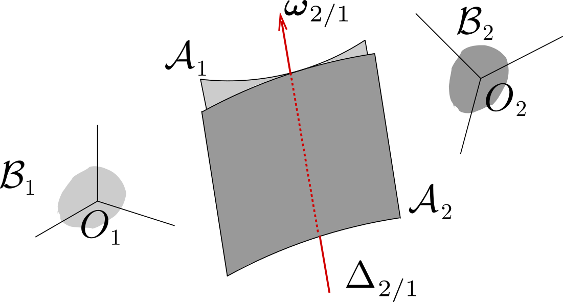
Recall that all points on \(\Delta_{2/1}\) have the same velocity \(p_{2/1} \, \bom_{2/1}\text{.}\) Axis \(\Delta_{2/1}\) is attached neither to \(\cB_1\) nor to \(\cB_2\text{.}\) See Figure 7.3.7.
Figure 7.3.7. The fixed and moving axodes.

Definition 7.3.8. Fixed and Moving Axodes.

During the motion of body \(\cB_2\) relative to body \(\cB_1\text{,}\) the instantaneous screw axis \(\Delta_{2/1}\) generates two ruled surfaces \(\cA_1\) (relative to \(\cB_1\)) and \(\cA_2\) (relative to \(\cB_2\)), called fixed and moving axodes, respectively. The velocity field of body \(\cB_2\) relative to \(\cB_1\) is identical to that of ruled surface \(\cA_2\) in line contact with ruled surface \(\cA_1\) along \(\Delta_{2/1}\text{.}\)
Consider a “contact point” \(I\) between \(\cA_2\) and \(\cA_1\text{,}\) that is, a particular point of \(\Delta_{1/2}\text{.}\) We can describe the motion of \(\cB_2\) relative to \(\cB_1\) equivalently as the motion of axode \(\cA_2\) in line-contact with axode \(\cA_1\) in terms of sliding, pivoting and rolling components. More specifically, we can identify
  1. a sliding component along \(\Delta_{2/1}\) with slip velocity \(\vel_{I\in 2/1} = p_{2/1} \bom_{2/1}\text{,}\)
  2. a vanishing pivoting component, since \(\bom^n_{2/1} = \bom_{1/2}\cdot\bn_{2/1} =0\text{,}\)
  3. a rolling component given by \(\bom^t_{2/1} = \bom_{2/1}\text{.}\)
Hence, two cases can be distinguished:
  1. if \(p_{2/1} = 0\) at all time, then \(\cA_2\) rolls without slipping (and without pivoting) relative to \(\cA_1\text{:}\) \(\cA_2\) is in instantaneous rotation about \(\Delta_{2/1}\) (the instantaneous axis of rotation).
  2. if \(p_{2/1} \neq 0\text{,}\) then \(\cA_2\) rolls about and slips along \(\Delta_{1/2}\) without pivoting relative to \(\cA_1\text{.}\)

Subsection 7.3.5 Examples

Example 7.3.9. Rolling Motion of a Cylindrical Tube.

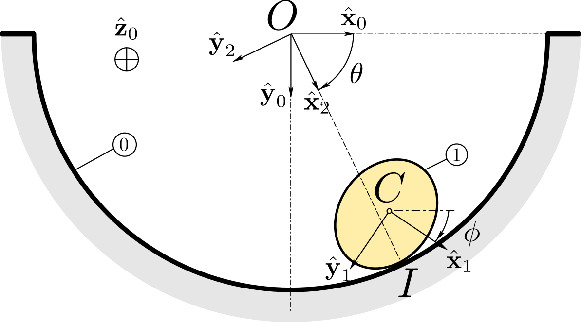
A cylinder \(\cB_1 (C, \bx_1 , \by_1 ,\bz_0)\) whose cross-section is not necessarily circular is in rolling motion on a right circular cylindrical support of a referential \(\cB_0 (O, \bx_0 , \by_0 , \bz_0)\text{.}\) See Figure 7.3.10.
Figure 7.3.10.
The boundary of \(\cB_1\) is defined as a closed curve defined as the set of points \(Q\) satisfying
\begin{equation*} \br_{CQ} (s) = f(s) \bx_1 + g(s)\by_1 \end{equation*}
where the given functions \(f\) and \(g\) are \(2\pi\)-periodic in the parameter \(s\text{.}\) The position of \(\cB_1\) is defined by
  1. the angle \(\phi = (\bx_0 , \bx_1) = (\by_0 , \by_1)\) defining the orientation of basis \((\bx_1 , \by_1 , \bz_1 = \bz_0 )\text{,}\)
  2. the angle \(\theta = (\bx_0 , \bx_2) = (\by_0 , \by_2)\) defining the position of contact point \(I\text{:}\) \(\br_{OI} = R \bx_2\text{.}\)
  1. Find the slip velocity \(\vel_{I\in 1/0}\) of body \(\cB_1\) relative to \(\cB_0\text{.}\) Deduce a geometric condition which guarantees contact at \(I\text{.}\) Then find velocity \(\vel_{C/0}\text{.}\)
  2. Assume that \(\cB_1\) rolls without slipping on \(\cB_0\text{.}\) Show that the no-slip condition can be reduced to a holonomic constraint equation. Then consider the case of (i) a circular cylinder \((f,g)= (r\cos s, r\sin s)\text{,}\) and (ii) of an elliptic cylinder \((f,g)= (a\cos s, b\sin s)\text{.}\)
Solution.
  1. The contact velocity \(\vel_{I\in 1/0}\) can be found as follows
    \begin{equation*} \vel_{I\in 1/0} = \vel_{I/0}- \vel_{I/1} \end{equation*}
    where velocity \(\vel_{I/0}\) found as \((d\br_{OI} /dt)_0\)
    \begin{equation*} \vel_{I/0}= \left( \frac{ d (R \bx_2)}{dt} \right)_0 = R \dte \by_2 \end{equation*}
    Likewise, velocity \(\vel_{I/1}\) is found as the time-derivative of \(\br_{CI}\) relative to body \(\cB_1\text{.}\) Since the trajectory of \(I\) relative to \(\cB_1\) lies on the boundary of \(\cB_1\text{,}\) we can write \(\br_{CI} = f(s) \bx_1 + g(s)\by_1\) where scalar \(s= s(t)\) parametrizes the position of \(I\text{.}\) This leads to
    \begin{equation*} \vel_{I/1}= \left( \frac{d}{dt} (f(s) \bx_1 + g(s)\by_1) \right)_1 = \ds (f' \bx_1 + g' \by_1) \end{equation*}
    with \(f' = df/ds\text{,}\) \(g'= dg/ds\text{.}\) This gives
    \begin{equation*} \vel_{I\in 1/0} = R \dte \by_2 - \ds (f' \bx_1 + g' \by_1) \end{equation*}
    The slip-velocity \(\vel_{I\in 1/0}\) must be tangent at \(I\) with the contact line for the contact to be realized. Hence, we must impose \(\vel_{I\in 1/0} \cdot \bx_2 = 0\text{.}\) This gives the equation
    \begin{equation*} - \ds (f' \bx_1 + g' \by_1)\cdot \bx_2 = -\ds (f' \cos(\theta -\phi) + g' \sin(\theta -\phi) ) =0 \end{equation*}
    which can be recast as
    \begin{equation*} \tan(\theta -\phi) = G(s) = - \frac{f'(s)}{g'(s)} \qquad (1) \end{equation*}
    This relationship enables the determination of the position of \(I\) (and hence of \(C\)) as a function of angle \((\theta - \phi)\text{.}\) From equation
    \begin{equation*} \br_{OC} = \br_{OI}+ \br_{IC} = R\bx_2 -f \bx_1 -g \by_1 \end{equation*}
    we obtain the velocity of \(C\text{:}\)
    \begin{equation*} \vel_{C/0} = R \dte \by_2 - \ds (f' \bx_1 +g' \by_1) + \dphi (f \by_1 - g \bx_1) \end{equation*}
    with \(G'(s) \ds = (\dte - \dphi)/\cos^2 (\theta - \phi)\) by differentiation of (1).
  2. The no-slip condition is imposed by setting \(\vel_{I\in 1/0} = \bze\text{:}\)
    \begin{equation*} R \dte = \ds (- f'\sin(\theta -\phi) + g'\cos(\theta -\phi) ) \end{equation*}
    This equation imposes a relationship between \(\phi\) and \(\theta\text{.}\) This is an integrable non-holonomic constraint equation: by using (1) we can express \(\theta\) versus \(s\)
    \begin{equation*} R(\te -\te_0) = \int_{s_0}^s (f'^2 + g'^2)^{1/2} ds \qquad(2) \end{equation*}
    \(\te_0\) and \(s_0\) are constants of integration. For the circular cylinder, we find from (2) \(R\dte = r \ds\) and from (1) \(\tan(\te-\phi) = \tan s\) or \(\dte - \dphi = \ds\) leading to
    \begin{equation*} \phi - \phi_0 = (1+\frac{R}{r}) (\te -\te_0 ) \end{equation*}
    For the elliptic cylinder, (2) gives \(\te\) versus \(s\)
    \begin{equation*} R(\te -\te_0) = \int_{s_0}^s (a^2 \sin^2 s + b^2 \cos^2 s)^{1/2} ds \end{equation*}
    and (1) gives \(\phi\) versus \(s\text{.}\) We can also find a quadrature formula giving \(\te\) versus \(\phi\) by eliminating \(s\text{:}\)
    \begin{equation*} R(\te -\te_0) = \int_{\psi_0}^\psi \frac{a^2b^2}{(a^2 \cos^2 u + b^2 \sin^2 u)^{3/2}} du \end{equation*}
    by defining \(\psi = \te-\phi\) and \(\psi_0 = \te_0-\phi_0\text{.}\) In both cases, we recognize that equation (2) expresses the equality of arc length of the two curves (the centrodes) described by \(I\) on the boundary of \(\cB_0\) and \(\cB_1\text{.}\)

Example 7.3.11. Rolling and pivoting of a disk on a horizontal support.

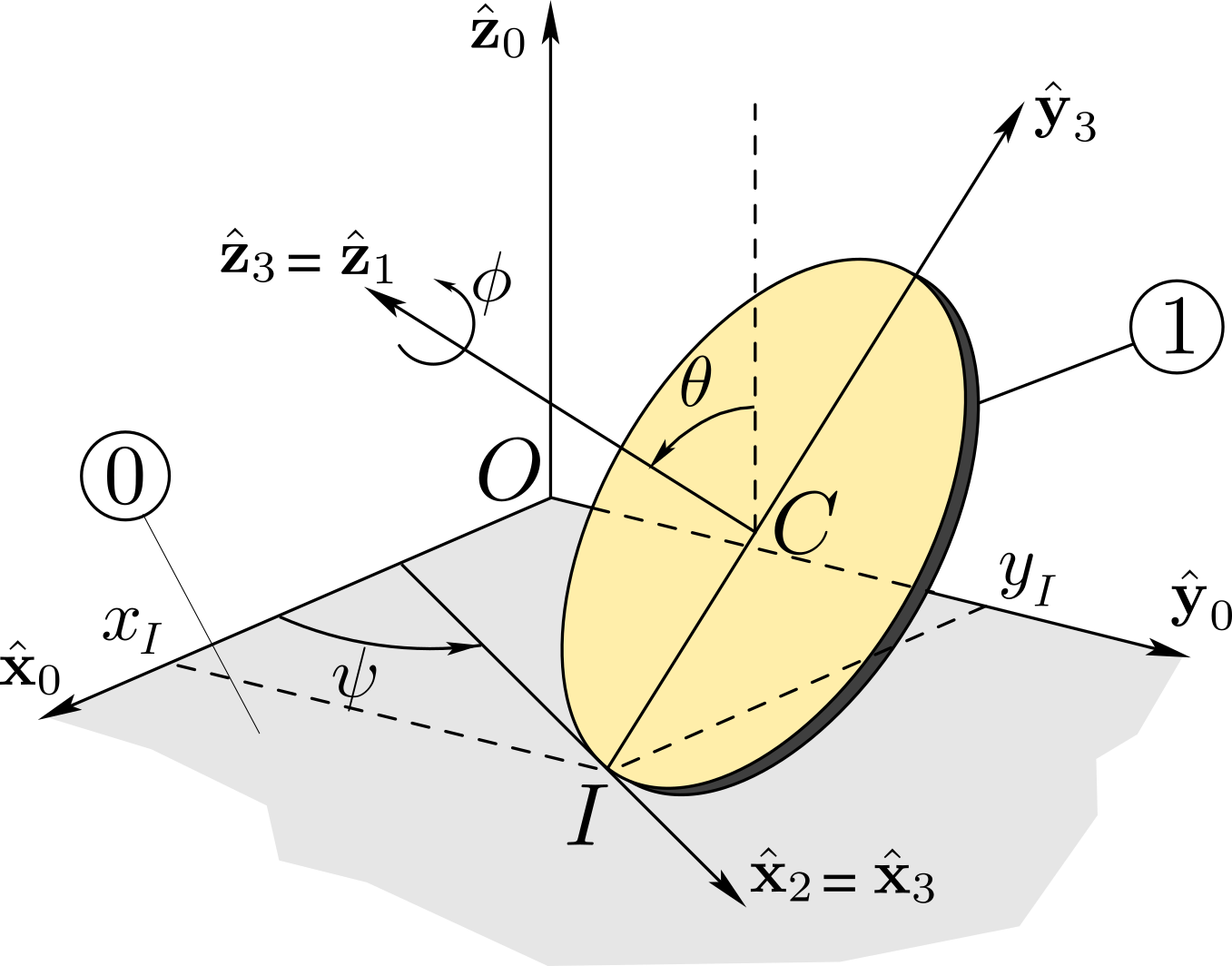
A disk \(\cB_1\) of center \(C\) and radius \(R\) is constrained to roll, pivot and slip about contact point \(I\) relative to horizontal plane \((O, \bx_0 , \by_0)\) of a referential \(\cB_0\text{.}\) Its position is defined by the coordinates \((x_I,y_I)\) of contact point \(I\) and by the three Euler angles \((\psi , \te , \phi)\) as defined in Figure 7.3.12.
Figure 7.3.12.
  1. Determine the kinematic screw of \(\cB_1\text{.}\) Find the pivoting and rolling components of the angular velocity of \(\cB_1\text{.}\) Find its angular acceleration.
  2. After finding the slip velocity \(\vel_{I\in 1 /0}\text{,}\) determine the kinematic constraint equations which express the no-slip condition of \(\cB_1\) relative to \(\cB_0\text{.}\) Can \(\cB_1\) roll without slipping and pivoting?
Solution.
  1. The parametrization of the position of disk \(\cB_1 (C, \bx_1, \by_1,\bz_1)\) relative to \(\cB_0 (O, \bx_0,\by_0,\bz_0)\) is done with the set of coordinates \((x_I, y_I, \psi, \te, \phi)\) defined as follows:
    1. \((x_I,\,y_I )\) are the Cartesian coordinates of contact point \(I\) on the axes \((O,\bx_0)\) and \((O,\by_0)\text{.}\)
    2. angle \(\psi\) defines the orientation of the line \((I, \, \bx_2)\) tangent at the point of contact \(I\) to the rim of the disk: \(\psi = (\bx_0,\bx_2)\text{.}\) This leads to the transformation
      \begin{equation*} (\bx_0 ,\by_0 , \bz_0) \xrightarrow{\cR_{\psi, \bz_0}} (\bx_2 ,\by_2 ,\bz_2 = \bz_0) \end{equation*}
    3. angle \(\te\) defines the orientation of the normal \((I, \bz_3)\) to disk \(\cB_1\text{:}\) \(\te = (\bz_0,\bz_3)\text{.}\) Then, we define \(\by_3 = \bz_3 \times \bx_2\) such that \(\br_{IC} = R \by_3\text{.}\) This leads to the transformation
      \begin{equation*} (\bx_2 ,\by_2 , \bz_0) \xrightarrow{\cR_{\te, \bx_2}} (\bx_3 = \bx_2 ,\by_3 , \bz_3) \end{equation*}
    4. the basis \((\bx_1 , \by_1, \bz_1 = \bz_3)\) attached to \(\cB_1\) is obtained from basis \((\bx_3 = \bx_2 , \by_3 , \bz_3)\) by a rotation of angle \(\phi = (\bx_2,\bx_1) = (\by_3,\by_2)\) about \(\bz_3\text{:}\)
      \begin{equation*} (\bx_2 ,\by_3 , \bz_3)\xrightarrow{\cR_{\phi, \bz_3}} (\bx_1 , \by_1, \bz_1 = \bz_3) \end{equation*}
    With this parametrization, we find the angular velocity of the disk
    \begin{equation*} \bom_{1/0} = \bom_{1/3} +\bom_{3/2}+ \bom_{2/0}=\dphi \bz_3+\dte \bx_2+ \dpsi \bz_0\text{.} \end{equation*}
    To find the pivoting component of \(\bom_{1/0}\text{,}\) we project \(\bom_{1/0}\) on the unit normal \(\bz_0\text{:}\)
    \begin{equation*} \bom^{n}_{1/0} = ( \bom_{1/0} \cdot \bz_0 ) \bz_0 = [(\dpsi \bz_0 + \dte \bx_2+ \dphi \bz_3) \cdot \bz_0 ] \bz_0 \end{equation*}
    or
    \begin{equation*} \bom^{n}_{1/0} = (\dpsi + \dphi\cos\te ) \bz_0 \end{equation*}
    The rolling component is then given by \(\bom_{1/0}^{t} = \bom_{1/0} - \bom_{1/0}^{n}\)
    \begin{equation*} \bom^{t}_{1/0} = \dte \bx_2 - \dphi \sin\te \by_2 \end{equation*}
    The angular acceleration of \(\cB_1\) relative to \(\cB_0\) can be found as:
    \begin{equation*} \bal_{1/0} = \ddphi \bz_3 + \ddte \bx_2 + \ddpsi \bz_0 + \dphi (\dte\bx_2+\dpsi\bz_0)\times \bz_3 + \dte \dpsi \by_2 \end{equation*}
    leading to, on basis \((\bx_3, \by_3, \bz_3)\)
    \begin{align*} \bal_{1/0} = (\ddte +\dpsi\dphi\sin\te)\bx_3 \amp + (\ddpsi \sin\te -\dte\dphi +\dpsi\dte \cos\te)\by_3\\ \amp \quad + (\ddphi + \ddpsi \cos\te - \dpsi\dte \sin\te)\bz_3 \end{align*}
    To write the kinematic screw \(\{ {\cal V} _{1/0 } \}\) of \(\cB_1\text{,}\) we need to find the velocity of center \(C\) by differentiating the position vector \(\br_{OC} = x_I \bx_0 + y_I \by_0 + R \by_3\text{:}\)
    \begin{align*} \vel_{C / 0} \amp = \dx_I \bx_0 + \dy_I \by_0 + R (\dte\bx_2+\dpsi\bz_0)\times \by_3\\ \amp = \dx_I \bx_0 + \dy_I \by_0 +R (\dte \bz_3 -\dpsi\cos\te\bx_3) \end{align*}
    This leads to the expression
    \begin{equation*} \{ {\cal V} _{1/0 } \} = \begin{Bmatrix} \dphi \bz_3+\dte \bx_2+ \dpsi \bz_0 \\ \\ \dx_I \bx_0 + \dy_I \by_0 + R (\dte \bz_3 -\dpsi\cos\te\bx_3) \end{Bmatrix}_C \end{equation*}
  2. To find slip-velocity at \(I\text{,}\) that is, the velocity of the point of \(\cB_1\) coinciding with \(I\text{,}\) we use the kinematic screw formula:
    \begin{equation*} \vel_{I \in 1/0} = \vel_{C\in 1/0} + \bom _{1/0 } \times \br_{CI} = \vel_{C\in 1/0} + R (\dphi \bx_3 - \dte \bz_3 +\dpsi\cos\te\bx_3) \end{equation*}
    This gives, after simplifications,
    \begin{equation*} \vel_{I \in 1/0} = \dx_I \bx_0 + \dy_I \by_0 + R \dphi \bx_3 \qquad(1) \end{equation*}
    Note that the condition \(\vel_{I\in 1/0} \cdot \bz_0 =0\) is satisfied since the parametrization in terms of \((x_I,y_I,\psi,\theta, \phi)\) takes into account the condition of contact at \(I\text{.}\) The expression of the slip-velocity can be used to define the kinematic screw of \(\cB_1\text{:}\)
    \begin{equation*} \{ {\cal V}_{ 1/0 } \} = \begin{Bmatrix} \dphi \bz_3+\dte \bx_2+ \dpsi \bz_0 \\ \\ \dx_I \bx_0 + \dy_I \by_0 + R\dphi \bx_3 \end{Bmatrix}_I \end{equation*}
    If \(\cB_1\) rolls and pivots without slipping on \(\cB_0\text{,}\) then \(\vel_{I \in 1/0}= {\bf 0}\text{:}\) we project equation (1) on \((\bx_0, \by_0)\) to obtain the following two non-holonomic constraints equations
    \begin{equation*} \begin{array}{ll} \dx_I \amp = -R \dphi \cos\psi \\ \dy_I \amp = -R \dphi \sin\psi \end{array} \end{equation*}
    These equations are non-integrable. For \(\cB_1\) to roll without slipping and pivoting, a third non-holonomic equation must be imposed:
    \begin{equation*} \dpsi + \dphi\cos\te = 0 \end{equation*}
Remark 7.3.13.
We could have found \(\vel_{I \in 1/0}\) as the difference \(\vel_{I/0} -\vel_{I/1}\) with
\begin{equation*} \vel_{I/0} = (d \br_{OI} /dt)_0 = \dx_I \bx_0 + \dy_I \by_0 \end{equation*}
and
\begin{equation*} \vel_{I/1} = (d \br_{CI} /dt)_1 = -R \bom_{3/1}\times \by_3 = R \dphi \bz_3 \times \by_3 = -R \dphi \bx_3 \end{equation*}
We recover the same expression.

Example 7.3.14.

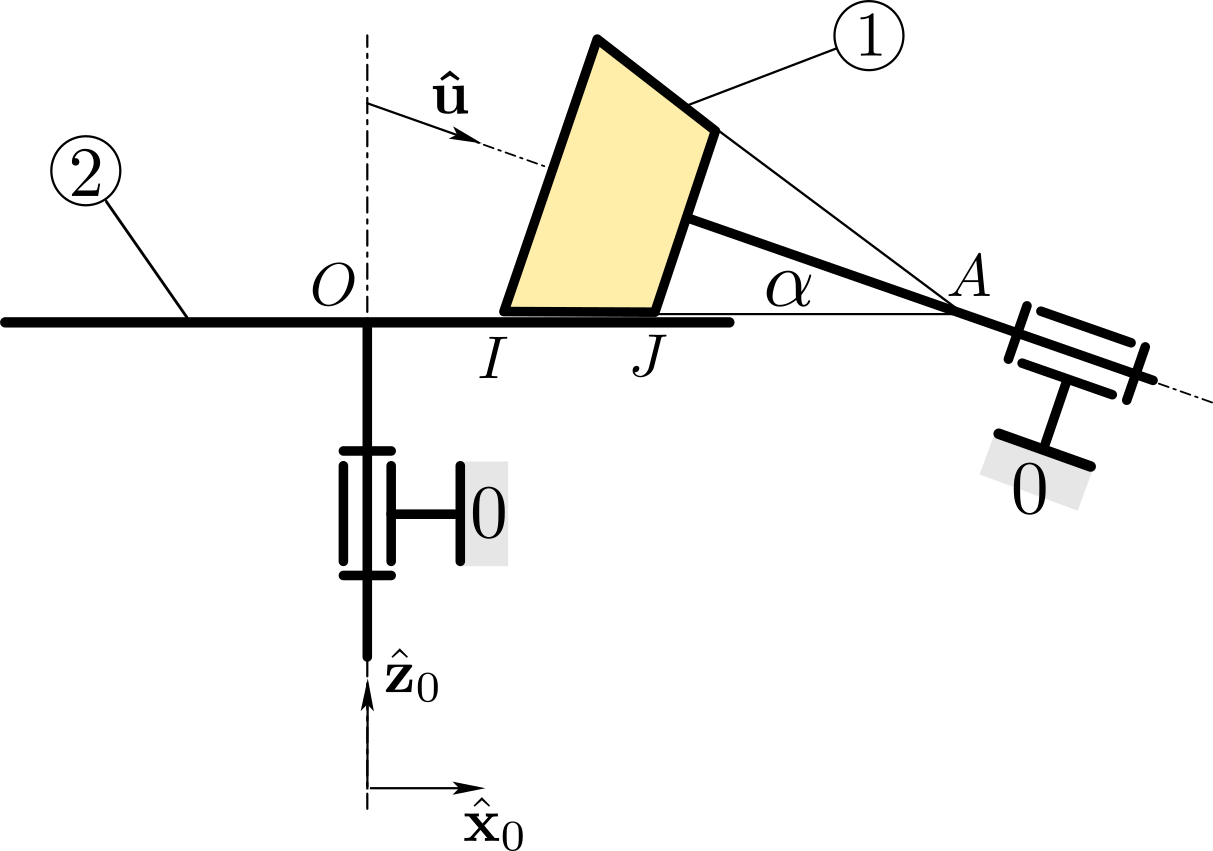
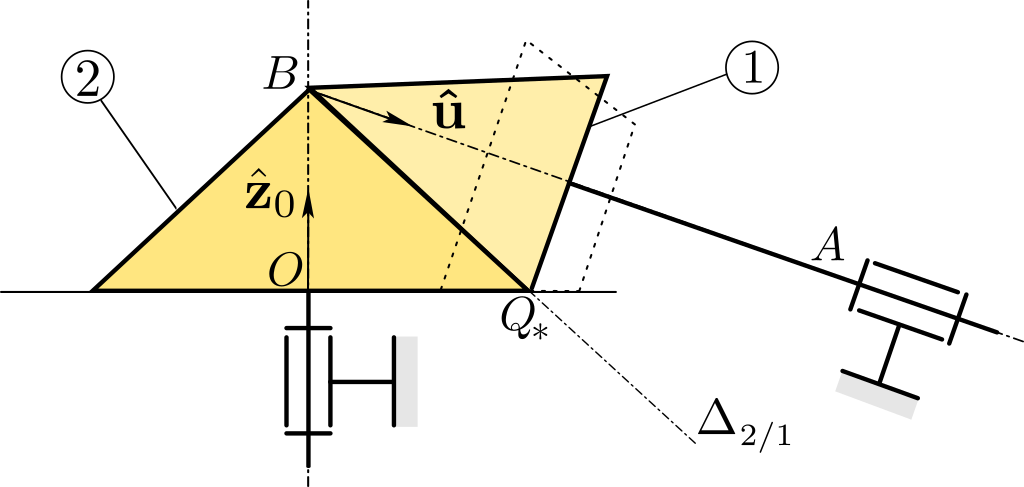
Figure 7.3.15 shows two rigid bodies \(\cB_1\) and \(\cB_2\) in relative motion in a referential \(\cB_0\) of origin \(O\) and basis \((\bx_0 , \by_0 , \bz_0 )\text{.}\) Body \(\cB_1\) is a truncated cone (of half-angle \(\alpha\text{.}\) connected to \(\cB_0\) by a pivot of axis \((A , \bu)\) (the axis of the cone) whose orientation in \(\cB_0\) is defined by angle \(\alpha\text{.}\) The angular velocity of body \(\cB_1\) is \(\bom_{1/0} = \omega_1 \bu\text{.}\) Body \(\cB_2\) is a circular platform mounted on a pivot of axis \((O, \bz_0)\text{:}\) its angular velocity is \(\bom_{2/0} = \omega_2 \bz_0\text{.}\) The two bodies are in contact along the line segment \(IJ\text{.}\) Figure 7.3.15 represents the plane containing both axes \((A, \bu)\) and \((O, \bz_0)\text{.}\) Denote by \(a\) the distance \(|OA|\text{.}\)
Figure 7.3.15.
  1. Find the angular velocity \(\bom_{2/1}\) of body \(\cB_2\) relative to body \(\cB_1\text{.}\) Decompose \(\bom_{2/1}\) into rolling and pivoting components.
  2. Express the kinematic screw \(\{ {\cal V}_{2/1} \}\) at a point of your choice.
  3. Find the velocity \(\vel_{Q \in 2/1}\) of any point \(Q\) of the contact line \(OA\text{.}\) Deduce that the instantaneous screw axis \(\Delta_{2/1}\) passes through two points in the plane of the figure. What is the corresponding velocity of points of the screw axis? Describe the two axodes generated by the motion of \(\Delta_{2/1}\) relative to \(\cB_1\) and to \(\cB_2\text{,}\) then characterize the motion of \(\cB_2\) relative to \(\cB_1\) in terms of the relative motion of the axodes.
Solution.
  1. We obtain \(\bom_{2/1}\) by taking the difference between \(\bom_{2/0}\) and \(\bom_{1/0}\text{:}\)
    \begin{equation*} \bom_{2/1} = \bom_{2/0}- \bom_{1/0} = \om_2 \bz_0 - \om_1 \bu = (\om_2 + \om_1 \sin\alpha) \bz_0 - \om_1 \cos\alpha \bx_0 \end{equation*}
    Since the two surfaces in contact (along line \(IJ\)) have a common normal along \(\bz_0\text{,}\) the pivoting component of \(\bom_{2/1}\) is \((\om_2 + \om_1 \sin\alpha) \bz_0\) and the rolling component is \(- \om_1 \cos\alpha \bx_0\text{.}\)
  2. We first define \(\by_0 = \bz_0 \times \bx_0\text{.}\) We obtain kinematic screw \(\{ \cV_{2/1} \}\) as the difference between \(\{ \cV_{2/0} \}\) and \(\{ \cV_{1/0} \}\text{:}\)
    \begin{equation*} \{ \cV_{2/1} \} = \{ \cV_{2/0} \} - \{ \cV_{1/0} \} \end{equation*}
    Since the joint between \(\cB_1\) and \(\cB_0\) is a pivot of axis \((A, \bu)\text{,}\) we have:
    \begin{equation*} \{ \cV_{1/0} \} = \begin{Bmatrix} \om_1 \bu \\ \\ \bze \end{Bmatrix}_{A} \end{equation*}
    Similarly, the joint between \(\cB_2\) and \(\cB_0\) is a pivot of axis \((O, \bz_0)\text{:}\)
    \begin{equation*} \{ \cV_{2/0} \} = \begin{Bmatrix} \om_2 \bz_0 \\ \\ \bze \end{Bmatrix}_{O} \end{equation*}
    This leads to
    \begin{equation*} \{ \cV_{2/1} \} = \begin{Bmatrix} \om_2 \bz_0 \\ \\ \bze \end{Bmatrix}_{O} - \begin{Bmatrix} \om_1 \bu \\ \\ \bze \end{Bmatrix}_{A} = \begin{Bmatrix} \om_2 \bz_0 - \om_1 \bu \\ \\ -a \om_1 \sin\alpha \by_0 \end{Bmatrix}_{O} \end{equation*}
    where we have used \(\vel_{O\in 1/0}= \om_1 \bu \times \br_{AO} = - \om_1 \bu \times a \bx_0 = a \om_1 \sin\alpha \by_0\text{.}\)
  3. First, we define the position of an arbitrary point on line OA as \(\br_{OQ} = \lambda \bx_0\) (\(\lambda\) is arbitrary scalar). We find \(\vel_{Q\in 2/1}\) by using the kinematic screw found in b):
    \begin{equation*} \vel_{Q\in 2/1} = \vel_{O\in 2/1}+ \bom_{2/1} \times \br_{OQ} = -a \om_1 \sin\alpha \by_0 + (\om_2 \bz_0 - \om_1 \bu) \times \lambda \bx_0 \end{equation*}
    leading to
    \begin{equation*} \vel_{Q\in 2/1} = [-a \om_1 \sin\alpha + \lambda (\om_2 + \om_1 \sin\alpha) ]\by_0 \end{equation*}
    Note the direction of \(\vel_{Q\in 2/1}\text{:}\) it has no component on \(\bz_0\text{,}\) as expected. We also note that \(\vel_{Q\in 2/1}\) has a non zero value for all points \(Q\) of line \(OA\) except if scalar \(\lambda\) takes the value
    \begin{equation*} \lambda_* = a \frac{\om_1 \sin\alpha}{\om_2 + \om_1 \sin\alpha } \end{equation*}
    We call \(Q_*\) the corresponding point: \(\vel_{Q_* \in 2/1} = \bze\) (this point lies between \(O\) and \(A\) if scalars \(\om_1\) and \(\om_2\) are both positive). The existence of point \(Q_*\) indicates that screw axis \(\Delta_{2/1}\) is an instantaneous axis of rotation since it passes through \(Q_*\text{.}\) Note that the corresponding pitch is necessarily zero. Another point of interest is point \(B\) defined as the intersection of the rotation axes \((A, \bu)\) and \((O, \bz_0)\text{:}\) since \(B\) belongs to both axes, we have
    \begin{equation*} \vel_{B\in 2/1} = \vel_{B\in 2/0} - \vel_{B\in 1/0} = \bze \end{equation*}
    Hence, point \(B\) must also belong to axis \(\Delta_{2/1}\text{:}\) we conclude that \(\Delta_{2/1}\) is the line \(BQ_*\text{.}\) This axis is fixed relative to referential \verb=0=. Relative to body \(\cB_2\text{,}\) it generates a cone of axis \((B, \bz_0)\) and apex \(B\text{.}\) Similarly, \(\Delta_{2/1}\) viewed from body \(\cB_1\) generates a cone of axis \((B, \bu)\) and apex \(B\text{.}\) The motion body \(\cB_2\) relative to body \(\cB_1\) (as far as velocities are concerned) is then equivalent to the motion of a cone of \(\cB_1\) rolling without slipping on a cone of \(\cB_2\text{.}\) See Figure 7.3.16 for a sketch of these two axodes.
Figure 7.3.16.