Section 7.1 Constraints Between Rigid Bodies

Subsection 7.1.1 Geometric versus kinematic constraints

Recall from Chapter 1 that the parametrization of the position of a rigid body \(\cB_2\) relative to rigid body \(\cB_1\) can be achieved by parametrizing
  1. the position of a particular point \(O_2\) attached to \(\cB_2\text{,}\) and
  2. (the orientation of a basis \((\bx_2 , \by_2 , \bz_2)\) attached to \(\cB_2\) relative to a basis \((\bx_1 , \by_1 , \bz_1)\) attached to \(\cB_1\text{.}\)
In general, it takes six independent coordinates \(\bq (t)= (q_1 (t) , \ldots , q_6 (t))\) to define the unconstrained motion of \(\cB_2\) relative to \(\cB_1\text{.}\) However, if this motion is constrained, there must exist relationships between these coordinates and possibly between their time-derivatives, thereby restricting the mobility of \(\cB_2\) relative to \(\cB_1\text{.}\)
Two broad types of constraints can be defined:

Definition 7.1.1. Holonomic Constraints.

Constraints which lead to equations of the type
\begin{equation} f(\bq, t ) = 0\tag{7.1.1} \end{equation}
are said to be holonomic constraints.
They are also referred to as geometric constraints when the variable \(t\) is not explicit in (7.1.1). Geometric constraints typically appear when one or more points of \(\cB_2\) have a constrained motion relative to \(\cB_1\text{.}\) Whether they arise or not depends on the parametrization of the position of \(\cB_2\text{.}\)

Remark 7.1.2.

Various methods can be used to find geometric constraint equations as illustrated in these simple examples. A general scheme, known as Geometric Closure, consists of writing one or more vector loop equations between the position vectors of “special” points of the rigid bodies at play.

Definition 7.1.3. Non-Holonomic Constraints.

Constraints which lead to equations of the type
\begin{equation} f(\bq, \dot{\bq}, t ) = 0\tag{7.1.2} \end{equation}
are called non-holonomic or kinematic constraints.

Remark 7.1.4.

Constraint equations such as (7.1.2) are generally linear in the variable \(\dot{\bq}\text{,}\) that is, are of the type
\begin{equation} f_0 (\bq) + f_1 (\bq) \dot{q}_1 + \cdots + f_6 (\bq) \dot{q}_6 = 0 \tag{7.1.3} \end{equation}

Remark 7.1.5.

If by integration a non-holonomic constraint can be reduced to a holonomic one, the constraint is called pseudo-holonomic.

Remark 7.1.6.

As will be seen in Section 7.3, non-holonomic constraint equations can be the result of motions of \(\cB_2\) in point or line contact with \(\cB_1\text{,}\) such as rolling without slipping or rolling without pivoting.

Subsection 7.1.2 Examples of Geometric Constraints

The following examples illustrate methods to derive geometric constraint equations.

Example 7.1.7.

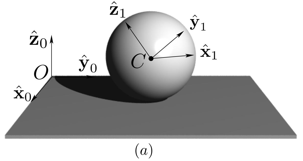
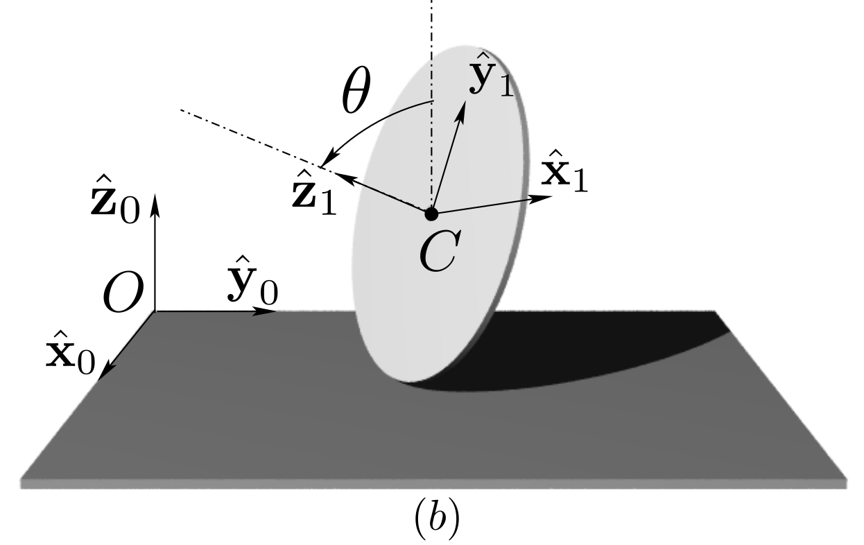
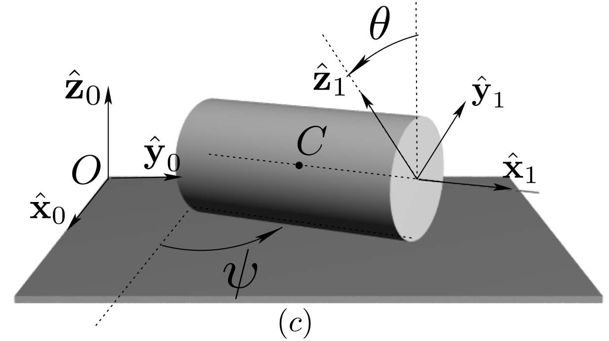
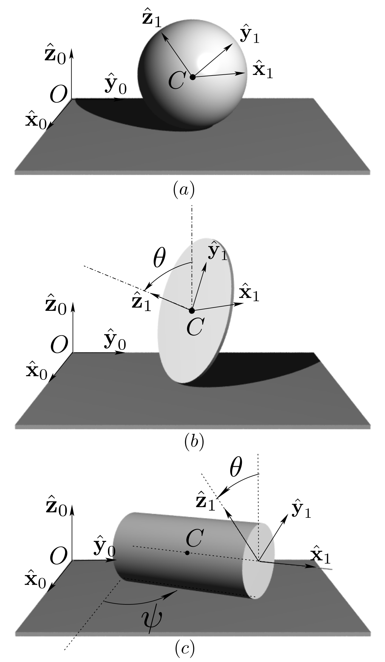
Figure 7.1.8 shows three examples of geometrically-constrained rigid bodies.
A sphere \(\cB_1\) (of center \(C\text{,}\) radius \(R\)) is constrained to move in a referential \(\cB_0 (O, \bx_0, \by_0, \bz_0 )\) in such a way as to remain in contact with plane \((O, \bx_0 , \by_0 )\text{.}\) After parametrizing the motion of \(\cB_1\) relative to \(\cB_0\text{,}\) find the equation(s) which express the constraint of \(\cB_1\) in \(\cB_0\text{.}\)
Repeat for the case of a disk in contact with plane \((O, \bx_0 , \by_0 )\) at a point of its rim, then for the case of a cylinder in contact with plane \((O, \bx_0 , \by_0 )\) along one of its generatrices.
Figure 7.1.8. Examples of geometrically-constrained rigid bodies.
Solution.
  1. The motion of sphere \(\cB_1\) shown in Figure 7.1.9. in contact with plane \((O, \bx_0 , \by_0)\) of referential \(\cB_0\) can be defined by specifying
    1. the three Cartesian coordinates \((x_C,y_C,z_C)\) of center \(C\text{:}\) \(\br_{OC} = x_C \bx_0 + y_C \by_0 + z_C \bz_0\text{,}\)
    2. the three Euler angles \((\psi , \te , \phi )\) defining the orientation of a basis \((\bx_1 , \by_1 , \bz_1)\) attached to \(\cB_1\) relative to basis \((\bx_0 , \by_0 , \bz_0)\) of \(\cB_0\text{.}\)
    Figure 7.1.9.
    The geometric constraint of contact at point \(I\) simply translates into the equation (project vector loop equation \(\br_{OI}+\br_{IC}+\br_{CO}=\bze\) on unit vector \(\bz_0\)):
    \begin{equation*} z_C = R \end{equation*}
    The remaining coordinates \((x_C , y_C ,\psi , \te , \phi )\) are in general independent. The number of degrees of freedom of \(\cB_1\) relative to \(\cB_0\) is reduced to 5. Additional constraints can be introduced depending on the nature of the contact, as will be seen in Subsection 7.3.2.
  2. Similarly, for a disk \(\cB_1\) of radius \(R\) in motion on a plane \((O, \bx_0 , \by_0)\text{,}\) there are two ways of parametrizing the position of the body.
    In the first method, the parametrization involves the two Cartesian coordinates \((x_I, y_I)\) of contact point \(I\) and the three Euler angles \((\psi , \te , \phi )\) defining the orientation of a basis \((\bx_1 , \by_1 , \bz_1)\) attached to \(\cB_1\) (angle \(\theta\) defines the inclination of the disk). Then, the position of the disk is fully specified: no constraint equation can be found between \((x_I,y_I,\psi , \te , \phi )\text{.}\)
    In the second method, the parametrization is achieved with the three Cartesian coordinates \((x_C, y_C, z_C)\) of center \(C\) along with the three Euler angles \((\psi , \te , \phi )\text{.}\) Now a constraint equation can be found by projecting vector loop equation \(\br_{OI}+\br_{IC}+\br_{CO}=\bze\) on unit vector \(\bz_0\) (see Figure 7.1.10):
    \begin{equation*} z_C = R \sin\theta \end{equation*}
    The number of degrees of freedom is reduced to 5.
    Figure 7.1.10.
  3. Finally, the parametrization of cylinder \(\cB_1\) relative to \(\cB_0\) can be done with Cartesian coordinates \((x_C , y_C , z_C)\) of a point \(C\) of the axis of \(\cB_1\) and the Euler angles \((\psi , \te , \phi)\) to define the orientation of basis \((\bx_1 , \by_1 , \bz_1)\) attached to \(\cB_1\) relative to a basis \((\bx_0 , \by_0 , \bz_0)\) of \(\cB_0\text{.}\) See Figure 7.1.11.
    Two constraint equations can be written (the motion of center \(C\) is planar):
    \begin{equation*} z_C = R , \qquad \phi =0 \end{equation*}
    If \(\bx_1\) denotes a unit vector of the axis of \(\cB_1\text{,}\) then basis \((\bx_1 , \by_1 , \bz_1)\) can be defined from basis \((\bx_0 , \by_0 , \bz_0)\) by the following sequence of rotations
    \begin{equation*} (\bx_0 , \by_0 , \bz_0) \xrightarrow{\cR_{\psi , \bz_0}} (\bx_1 , \bv , \bz_0) \xrightarrow{\cR_{\te , \bx_1}} (\bx_1 , \by_1 , \bz_1) \end{equation*}
    The number of degrees of freedom of \(\cB_1\) relative to \(\cB_0\) is reduced to four.
    Figure 7.1.11.

Example 7.1.12.

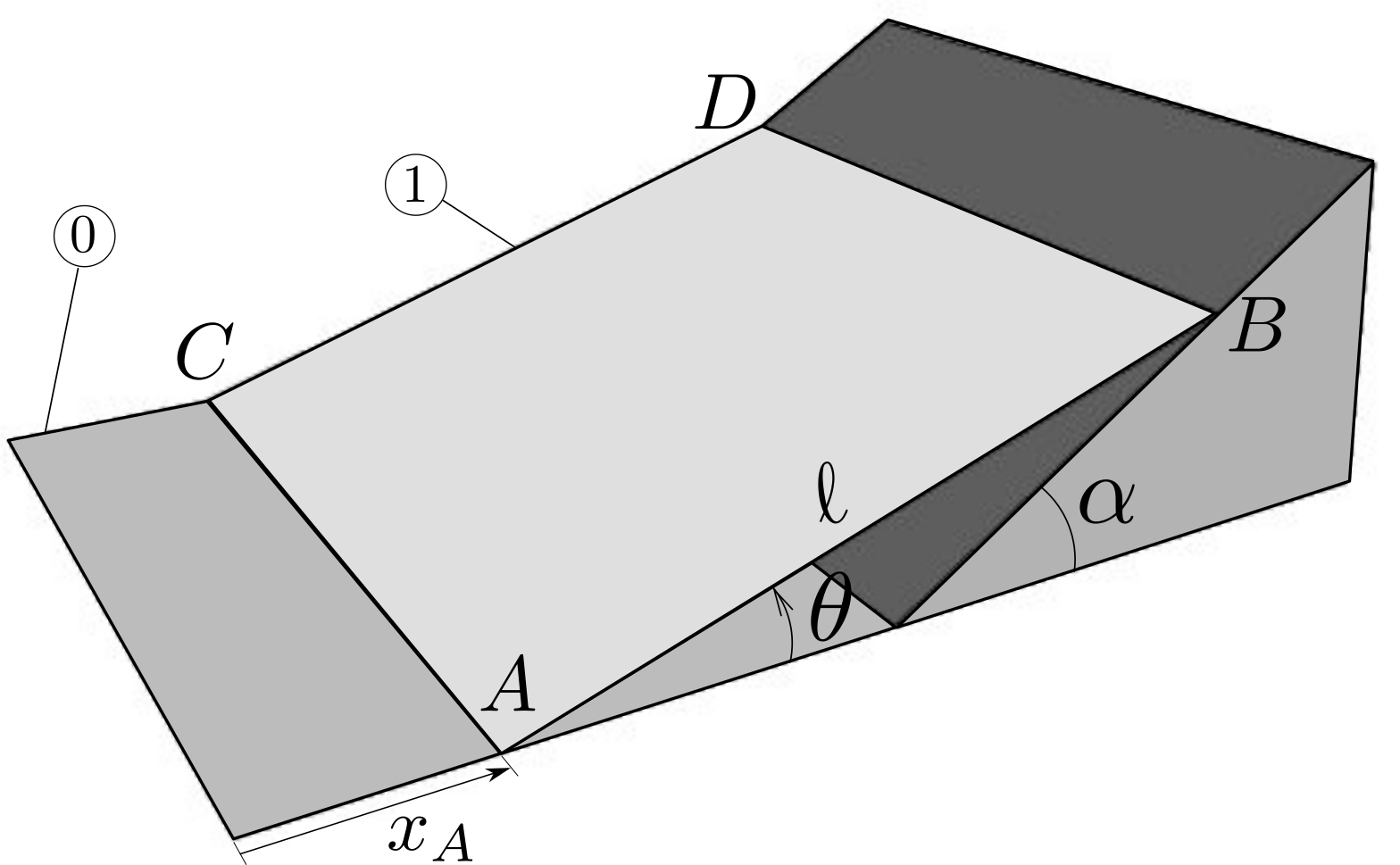
A plate \(\cB_1\) of side length \(\ell\) is constrained to slide on a planar support \(\cB_0\) along edge \(AC\) and on an inclined plane along edge \(BD\text{.}\) The motion is parametrized with the coordinates \(x_A\) and \(\theta\text{,}\) as shown in Figure 7.1.13.
Find the constraint equation between \(x_A\) and \(\theta\text{.}\)
Figure 7.1.13.
Solution.
We define basis \((\bx_0 , \by_0 , \bz_0)\) attached to the fixed support such that position of corner point \(A\) is given by \(\br_{OA} = x_A \bx_0\text{,}\) and basis \((\bx_1 , \by_1, \bz_0)\) attached to \(\cB_1\) such that position of corner point \(B\) is given by \(\br_{AB} =\ell \bx_1\text{.}\) See Figure 7.1.14.
Figure 7.1.14.
The coordinates \((x_A , \te)\) parametrize the motion of \(\cB_1\text{:}\) they are not independent, due to the constraint of point \(B\) with the inclined wall. Two methods can be used.
In the first method, the constraint can be stated by imposing that the velocity of point \(B\) must be directed along the inclined wall, that is, \(\vel_{B\in 1/0} \cdot \bw =0\) (with \(\bw\) normal to the inclined wall). With
\begin{equation*} \vel_{B\in 1/0} = \vel_{A\in 1/0} + \dte \bz \times \ell\bx_1 = \dx_A \bx_0 + \ell \dte \by_1\text{,} \end{equation*}
we find
\begin{equation*} - \dx_A \sin\al + \ell \dte \cos(\al - \te ) =0 \end{equation*}
This is of course not a true kinematic constraint since it is integrable:
\begin{equation*} x_A \sin\al + \ell \sin(\al -\te) = \text{constant} \end{equation*}
In the second method, we impose the vector loop equation
\begin{equation*} \br_{OQ}= \br_{OA}+\br_{AB}+\br_{BQ} \end{equation*}
to obtain (by projection on \((\bx_0, \by_0)\)):
\begin{equation*} |OQ| = x_A + \ell \cos\te - |QB| \cos\al,\quad 0= \ell \sin\te - |QB|\sin\al \end{equation*}
We then obtain the geometric constraint
\begin{equation*} |OQ| \sin\al = \text{constant} = x_A \sin\al + \ell \sin(\al -\te) \end{equation*}

Example 7.1.15.

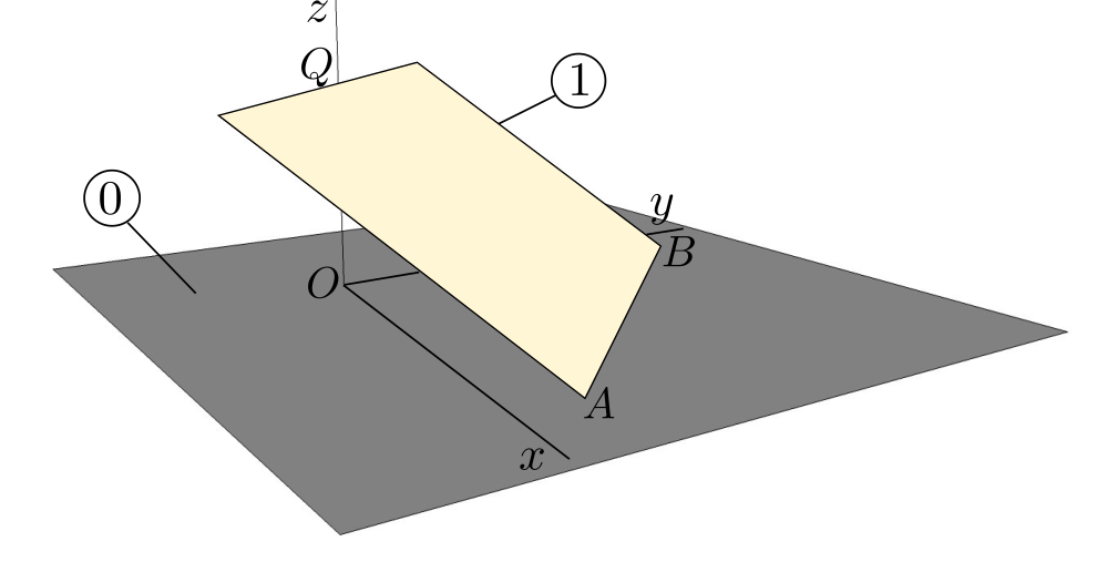
A square plate \(\cB_1\) of side length \(a\) is motion in a referential \(\cB_0\) in such a way that its lower edge \(AB\) slides in the plane \(Oxy\) of \(\cB_0\text{,}\) and that its upper edge slides along axis \(Oz\) normal to plane \(Oxy\text{.}\) See Figure 7.1.16.
Figure 7.1.16.
  1. Parametrize the position of \(\cB_1\) relative to \(\cB_0\text{.}\)
  2. Find the possible constraint equations.
  3. Then determine the kinematic screw of \(\cB_1\) relative to \(\cB_0\text{.}\)
Solution.
  1. To define the orientation of a basis \((\bx_1 , \by_1 , \bz_1)\) of \(\cB_1\) relative to basis \((\bx_0 , \by_0 , \bz_0)\text{,}\) we first define unit vector \(\bx_1\) along edge \(AB\text{,}\) such that \(\br_{AB} = a \bx_1\text{.}\) The orientation of line \(AB\) is defined by angle \(\te\) as shown in Figure 7.1.17, and such that \(\bx_1 = - \sin\te \bx_0 + \cos\te \by_0\text{.}\) The position of point \(A\) is defined by its Cartesian coordinates \((x_A , y_A)\text{:}\)
    \begin{equation*} \br_{OA}= x_A \bx_0 + y_A \by_0\text{.} \end{equation*}
    Figure 7.1.17.
    We then define point \(D\) as the projection of point \(O\) onto line \(AB\text{.}\) Finally, the inclination of \(\cB_1\) is defined by introducing angle \(\phi\) such that the contact point \(Q\) of \(\cB\) with axis \(Oz\) is defined by
    \begin{equation*} \br_{DQ}= a \bz_1= a(\sin\phi \bz_0 - \cos\phi \bv) \end{equation*}
    Unit vector \(\by_1 = \bz_1\times \bx_1\) is normal to plate \(\cB_1\text{.}\) See Figure 7.1.17.
  2. There must exist a constraint equation between the coordinates \((x_A , y_A , \te , \phi)\text{.}\) We write the vector loop equation between points \(O,A,D,Q\text{:}\)
    \begin{equation*} \br_{OA}+\br_{AD}+\br_{DQ}+\br_{QO}=\bze \end{equation*}
    or (with \(d= |AD|\) and \(z_Q=|OQ|\))
    \begin{equation*} x_A \bx_0 + y_A \by_0 + d \bx_1 + a\bz_1 - z_Q \bz_0 =\bze \end{equation*}
    By projection on basis \((\bx_1,\bv,\bz_0)\text{,}\) we find 3 relationships
    \begin{align*} -x_A \sin\te + y_A \cos\te +d = 0 \amp \qquad (1)\\ x_A \cos\te + y_A \sin\te = a \cos\phi \amp \qquad (2)\\ z_Q= a \sin\phi \amp \qquad (3) \end{align*}
    Equation (2) is the constraint equation we seek.
  3. This shows that body \(\cB_1\) has 3 degrees of freedom. With this parametrization, the kinematic screw of \(\cB_1\) is given by
    \begin{equation*} \{ {\cal V} _ {1 / 0} \} = \left\{ \begin{array}{c} \dte \bz_0 + \dphi \bx_1 \\ \dx_A \bx_0 + \dy_A \by_0 \end{array} \right\}_A \end{equation*}

Example 7.1.18. Axial Piston Pump.

Figure 7.1.19 shows a sketch of a variable-displacement axial piston pump.
  1. Body 0 \((O, \bx_0, \by_0, \bz_0)\) denotes the pump housing. A piston thrust plate is attached to 0 and is inclined with constant angle \(\alpha\text{.}\) The value of angle \(\alpha\) can be adjusted to vary the pump volumetric volume.
  2. Body 1 is the rotationally-driven pump barrel: it is rotating relative to 0= about axis \((A, \bx_0)\text{.}\) Body 2 is a piston connected to 1 by sliding along axis \((B, \bx_0)\text{.}\) Only one piston is shown in the diagram. Piston 2 is in contact at all time with the inclined thrust plate at a point \(J\text{.}\) A spring (not shown) guarantees that contact is always realized.
The motion of this mechanism is parametrized by oriented angle \(\theta (t) = (\bz_0 , \bz_1)\text{.}\) The displacement of the piston relative to the pump barrel is defined by the variable \(x(t) = \br_{JB} \cdot \bx_0\text{.}\)
Find the relationship between \(x\text{,}\) \(\theta\text{,}\) and the constants \(\alpha\text{,}\) \(R= \br_{AB} \cdot \bz_1\text{,}\) and \(d = \br_{OA}\cdot \bx_0\text{.}\)
Figure 7.1.19.
Solution.
To find the input-output law \(x= f(\theta)\text{,}\) we need to relate the position of points \(O\text{,}\) \(A\text{,}\) \(B\text{,}\) and \(J\) to one another. A possible method is to write the vector loop equation between these points:
\begin{equation*} \br_{OA}+\br_{AB} + \br_{BJ} + \br_{JO} = \bze \end{equation*}
with \(\br_{OA} = d \bx_0\text{,}\) \(\br_{AB} = R \bz_1\) and \(\br_{BJ} = -x \bx_0\text{.}\) The expression of \(\br_{OJ}\) is found by imposing that point \(J\) lies in the plane \((O, \by_0, \bw_0)\) of the thrust plate. Vector \(\bw_0 = \cos\alpha \bz_0 - \sin\alpha \bx_0\) is a unit vector of the plane of contact normal to \(\by_0\text{.}\) Thus we can write
\begin{equation*} \br_{OJ} = y_J \by_0 + w_J \bw_0 \end{equation*}
We arrive at the following vector equation
\begin{equation*} d \bx_0+ R \bz_1 -x \bx_0 - y_J \by_0 - w_J (\cos\alpha \bz_0 - \sin\alpha \bx_0) = \bze \end{equation*}
giving 3 scalar equations
\begin{align*} d -x + w_J \sin\alpha = 0 \amp \qquad (1)\\ R \sin\theta - y_J = 0\amp \qquad (2)\\ R\cos\theta - w_J \cos\alpha = 0\amp \qquad (3) \end{align*}
By using equations (1) and (3), we find the input-output law
\begin{equation*} x = d + R \cos\theta \tan\alpha \end{equation*}