Section 13.4 Lagrange Equations: Single Body

Consider a rigid body in motion in a Newtonian referential \(\cE\text{.}\) Assume that its configuration is defined by \(n\) coordinates \((q_1, \ldots, q_n)\) and time \(t\) satisfying the assumption (13.1.2). Recall from Section 11.1 that the Principle of Virtual Power takes the form:
\begin{equation} \{ \cD_{\cB/\cE} \} \cdot \{ \cV^* \} = \{\cA_{\coB \to \cB}\} \cdot \{ \cV^* \} \tag{13.4.1} \end{equation}
for any virtual kinematic screw \(\{ \cV^* \}\text{.}\) Lagrange equations are found by choosing the virtual kinematic screw as a linear combination of the partial kinematic screws of \(\cB\text{:}\)
\begin{equation*} \vel_P^* = \dq_1^* \frac{\partial \vel_P}{\partial \dq_1} + \cdots +\dq_n^* \frac{\partial \vel_P}{\partial \dq_n} \end{equation*}
which is equivalent to choosing \(\{ \cV^* \}\) as
\begin{equation} \{\cV^* \}= \dq_1^* \{\cV_{\cB/\cE}^{q_1}\} + \cdots +\dq_n^* \{\cV_{\cB/\cE}^{q_n}\} \tag{13.4.2} \end{equation}
The scalars \((\dq_1^*, \ldots, \dq_n^*)\text{,}\) known as virtual speeds, are arbitrary. Now equation (13.4.1) becomes
\begin{equation} \sum_{i=1}^n \dq_i^* \{ \cD_{\cB/\cE} \} \cdot\{\cV_{\cB/\cE}^{q_i}\} = \sum_{i=1}^n \dq_i^* \{\cA_{\coB \to \cB}\} \cdot\{\cV_{\cB/\cE}^{q_i}\}\tag{13.4.3} \end{equation}
The coefficients in the left-hand-side are found by using Lagrange kinematic formula (13.2.1)
\begin{align*} \{ \cD_{\cB/\cE} \} \cdot\{\cV_{\cB/\cE}^{q_i}\} \amp = \int_\cB \ba_P \cdot \frac{\partial \vel_P}{\partial \dq_i} dm = \int_\cB \ba_P \cdot \frac{\partial \br_{OP}}{\partial q_i} dm\\ \amp = \int_\cB \left[\frac{d}{dt}\left(\frac{\partial}{\partial \dq_i}\right) - \frac{\partial}{\partial q_i} \right] \frac{\vel_P^2}{2} dm\\ \amp = \left[\frac{d}{dt}\left(\frac{\partial}{\partial \dq_i}\right) - \frac{\partial}{\partial q_i} \right] \kin_{\cB/\cE} \end{align*}
where \(\kin_{\cB/\cE}\) is the kinetic energy of \(\cB\text{.}\) The right-hand-side of (13.4.3) is the virtual power \(\Pow^*_{\coB\to\cB/\cE}\) and can be expressed in terms of the power coefficients of the external action \(\{\cA_{\coB \to \cB}\}\)
\begin{equation*} \Pow^*_{\coB\to\cB/\cE} = \sum_{i=1}^n \dq_i^* \{\cA_{\coB \to \cB}\} \cdot\{\cV_{\cB/\cE}^{q_i}\} = \sum_{i=1}^n \dq_i^* \qQ_{\coB\to\cB /\cE} ^{q_i} \end{equation*}
Now equation (13.4.3) can be written as
\begin{equation} \sum_{i=1}^n \dq_i^* \left( \frac{d}{dt}\frac{\partial \kin_{\cB/\cE}}{\partial \dq_i} - \frac{\partial \kin_{\cB/\cE}}{\partial q_i} - \qQ_{\coB\to\cB /\cE} ^{q_i} \right) = 0 \label{}\tag{13.4.4} \end{equation}
Since the virtual speeds \((\dq_1^*, \ldots, \dq_n^*)\) are arbitrary, we can equate the \(i\)th coefficients of (13.4.4) to zero, yielding Lagrange equations (denoted \(\cL_{\cB/\cE}^{q_i}\text{.}\)
There are as many Lagrange equations as the number of coordinates chosen to parametrize the configuration of \(\cB\) relative to \(\cE\text{.}\) Before establishing guidelines for the derivation of Lagrange equations, we examine the solution of two examples.

Example 13.4.2.

Derive Lagrange equations \(\cL^{x}_{1/0}\) and \(\cL^{\te}_{1/0}\) for the plate of Example 13.3.7.
Solution.
To find these equations, we use the results found in Example 13.1.4 and Example 13.3.7. We first need to find the kinetic energy \(\kin_{1/0}\) in a manner compatible with assumption (13.1.2) which must be imposed to coordinates \((x,\theta)\text{:}\) recall that this is equivalent to ignoring the geometric constraint equation between the coordinates \(x\) and \(\theta\) which guarantees contact at corner point \(Q\text{.}\) This leads to the velocity
\begin{equation*} \vel_G = \vel_A + \dte\bz_0 \times l\bx_1 = \dx \bx_0 + l\dte\by_1 \end{equation*}
We can now find the expression of kinetic energy \(\kin_{1/0}\text{:}\)
\begin{align*} 2\kin_{1/0} \amp = m \vel_G^2 + I_{Gy} \dte^2 = m (\dx \bx_0 + l\dte\by_1)^2 + \tfrac{1}{3}ml^2 \dte^2\\ \amp = m \dx^2 - 2ml \dx\dte \sin\te+ \tfrac{4}{3}ml^2 \dte^2 \end{align*}
This leads to
\begin{align*} \left[\frac{d}{dt}\left(\frac{\partial}{\partial \dx}\right) - \frac{\partial}{\partial x} \right] \kin_{1/0} \amp = \frac{d}{dt} ( m\dx -ml\dte\sin\te)\\ \amp= m \ddx -ml \ddte \sin\te -ml \dte^2 \cos\te \end{align*}
\begin{align*} \left[\frac{d}{dt}\left(\frac{\partial}{\partial \dte}\right) - \frac{\partial}{\partial \te} \right] \kin_{1/0}\amp = \frac{d}{dt} (\tfrac{4}{3}ml^2 \dte- ml \dx \sin\te)+ ml \dx\dte \cos\te\\ \amp =\tfrac{4}{3}ml^2 \ddte- ml \ddx \sin\te \end{align*}
The two equations \(\cL^{x}_{1/0}\) and \(\cL^{\te}_{1/0}\) are then found by using the expressions of the power coefficients \(\qQ_{\bar{1}\to 1/0} ^x\) and \(\qQ_{\bar{1}\to 1/0} ^\te\text{:}\)
\begin{align*} \cL^{x}_{1/0}:\amp \quad m \ddx -ml \ddte \sin\te -ml \dte^2 \cos\te = F_A - N_Q \sin\te +F_Q \cos\te \amp \quad{(1)}\\ \cL^{\te}_{1/0}:\amp \quad \tfrac{4}{3}ml^2 \ddte- ml \ddx \sin\te = -mgl \cos\theta + \frac{h}{\sin\te} N_Q \amp \quad{(2)} \end{align*}
With \(F_A\) given, we have found two equations governing four unknowns: \(x\text{,}\) \(\theta\text{,}\) \(F_Q\) and \(N_Q\text{.}\) Hence, two additional equations must be given to complete the solution. The first equation is the geometric constraint equation
\begin{equation*} x + h \cot\theta = \text{const.} \qquad{(3)} \end{equation*}
The second equation is the relationship between \(F_Q\) and \(N_Q\)
\begin{equation*} |F_Q| = \mu N_Q \qquad{(4)} \end{equation*}
according to Coulomb law. The sign of \(F_Q\) is such that frictional force \(F_Q \bx_1\) opposes the slip velocity \(\vel_{Q\in 1/0}\text{.}\)

Example 13.4.3.

Derive the five Lagrange equations \(\cL^q_{1/0}\) governing the motion of the sphere of Example 13.3.8 for \(q=x,y,\psi,\theta,\phi\text{.}\)
Solution.
We can use the expressions of the power coefficients \(\qQ_{\bar{1}\to 1/0} ^q\) which were found in Example 13.3.8 by enforcing assumption (13.1.2) imposed on the coordinates \((x,y,\psi,\theta,\phi)\text{:}\) this is equivalent to ignoring the kinematic constraint \(\vel_{I\in 1/0}=\bze\) which guarantees no-slip at contact point \(I\text{.}\) It remains to find the kinetic energy \(\kin_{1/0}\) without violating assumption (13.1.2): we use the following expressions
\begin{equation*} \vel_G = \dx \bx_0 + \dy \by_0, \qquad \bom_{1/0} = \dpsi \bz_0 + \dte \bu + \dphi \bz_1 \end{equation*}
to find
\begin{equation*} 2\kin_{1/0} = m \vel_G^2 + \tfrac{2}{5} mr^2 \bom_{1/0}^2 = m(\dx^2 + \dy^2) + \tfrac{2}{5} mr^2 (\dpsi^2 +\dte^2 +\dphi^2 + 2\dpsi\dphi \cos\te) \end{equation*}
This leads to
\begin{align*} \left[\frac{d}{dt}\left(\frac{\partial}{\partial \dx}\right) - \frac{\partial}{\partial x} \right] \kin_{1/0} \amp = m \ddx\\ \left[\frac{d}{dt}\left(\frac{\partial}{\partial \dy}\right) - \frac{\partial}{\partial y} \right] \kin_{1/0} \amp = m \ddy\\ \left[\frac{d}{dt}\left(\frac{\partial}{\partial \dpsi}\right) - \frac{\partial}{\partial \psi} \right] \kin_{1/0} \amp = \tfrac{2}{5} mr^2 \frac{d}{dt} (\dpsi + \dphi \cos\te)\\ \left[\frac{d}{dt}\left(\frac{\partial}{\partial \dte}\right) - \frac{\partial}{\partial \te} \right] \kin_{1/0} \amp = \tfrac{2}{5} mr^2 (\ddte + \dpsi\dphi \sin\te)\\ \left[\frac{d}{dt}\left(\frac{\partial}{\partial \dphi}\right) - \frac{\partial}{\partial \phi} \right] \kin_{1/0} \amp = \tfrac{2}{5} mr^2 \frac{d}{dt} (\dphi + \dpsi \cos\te) \end{align*}
The five Lagrange equations \(\cL^q_{1/0}\) are then found by using the expressions of the power coefficients \(\qQ_{\bar{1}\to 1/0} ^q\) determined in Example 13.3.8:
\begin{align*} \cL^{x}_{1/0}:\amp \qquad m \ddx = F_u \cos\psi -F_v \sin\psi \quad\tag{1}\\\\ \cL^{y}_{1/0}:\amp \qquad m \ddy = F_u \sin\psi + F_v \cos\psi \quad\tag{2}\\\\ \cL^{\psi}_{1/0}:\amp \qquad \tfrac{2}{5} mr^2 \frac{d}{dt} (\dpsi + \dphi \cos\te) =0 \quad\tag{3}\\\\ \cL^{\te}_{1/0}:\amp \qquad \tfrac{2}{5} mr^2 (\ddte + \dpsi\dphi \sin\te) = rF_v \quad\tag{4}\\\\ \cL^{\phi}_{1/0}:\amp \qquad \tfrac{2}{5} mr^2 \frac{d}{dt} (\dphi + \dpsi \cos\te)= rF_u \sin\te \quad\tag{5} \end{align*}
We have found five equations governing seven unknowns \((x,y,\psi,\theta,\phi, F_u, F_v)\text{.}\) Hence, we are missing two equations. These equations are found by setting \(\vel_{I\in 1/0}=\bze\text{:}\)  1 
\begin{gather*} \dx = r\dte \sin\psi - r\dphi\sin\te\cos\psi \quad\tag{6}\\\\ \dy = -r\dte \cos\psi - r\dphi\sin\te \sin\psi \quad\tag{7} \end{gather*}
The solution is now complete.
We can now provide basic guidelines for the proper and efficient implementation of Lagrange equations.
  • Identify all coordinates \(q_i\) which define the configuration of the rigid body. The larger the set of coordinates, the better since more equations will be obtained. In particular, if a particular coordinate is an explicit function of time, it will advantageous to ignore this relationship: an additional Lagrange equation will be gained.  2 
  • Guarantee the assumption (13.1.2): this consists of ignoring all holonomic and non-holonomic equations which may exist between the coordinates.
  • Find all partial kinematic screws \(\{\cV^q_{\cB/\cE}\}\) in a manner consistent the assumption (13.1.2).
  • Identify all actions exerted on \(\cB\text{:}\) for each action, find the corresponding power coefficients \(\qQ^q\) for all \(q\)’s.
  • Determine the kinetic energy \(\kin_{\cB/\cE}\) in a manner consistent with assumption (13.1.2).
  • Derive Lagrange equations and bring back all constraint equations.
To emphasize point 2, we return to Example 13.4.2 and Example 13.4.3. In Example 13.4.2 it can be seen that the unknown normal reaction \(N_A\) is missing from the solution. This is due to the fact that the parametrization of the plate takes into account the contact at \(A\text{:}\) \(\br_{OA}\cdot \by_0 = y =0\text{.}\) We can alter the solution by ignoring the constraint \(y=0\) at \(A\text{.}\) We have now three coordinates \((x,y,\theta)\) assumed to satisfy assumption (13.1.2): we can verify that this does not change the expression of the power coefficients \(\qQ^x_{\bar{1}\to 1/0}\) and \(\qQ^\theta_{\bar{1}\to 1/0}\text{.}\) It is easy to show that the power coefficient \(\qQ^y_{\bar{1}\to 1/0}\) takes the expression \(N_A + N_Q \cos\te + F_Q \sin\te-mg\text{.}\) Similarly, the kinetic energy \(\kin_{1/0}\) must be corrected by the term \(\tfrac{m}{2}(\dy^2 +2 l\dy\dte\cos\te)\text{.}\) Lagrange equation \(\cL^y_{1/0}\) takes the form  3 
\begin{equation*} m \frac{d}{dt}(\dy + l \dte \cos\te) = N_A + N_Q \cos\te + F_Q \sin\te -mg \end{equation*}
We can now impose \(y=0\) and find \(N_A = mg - N_Q \cos\te - F_Q \sin\te\text{.}\)
In a similar manner, we can add Cartesian coordinate \(z= \bz_0 \cdot \br_{OG}\) for sphere 1 of Example 13.4.3 and ignore geometric constraint \(z=r\text{.}\) This new coordinate leaves equations \(\cL^q_{1/0}\) unchanged for \(q=x,y,\psi,\te,\phi\text{.}\) However, a new equation is found:
\begin{equation*} \cL_{1/0}^z: \qquad m \ddz = N-mg \end{equation*}
After imposing \(z=r\text{,}\) we find \(N=mg\text{.}\)
Of course, the procedure consisting of introducing “fictitious” coordinates to derive additional Lagrange equations is clumsy and can significantly complicate the solution. It can also be argued that this destroys the elegance of Lagrange formalism which in fact eliminates the presence of non-working mechanical action thanks to vanishing power coefficients. If equations are missing to solve for particular unknown quantities, it is best to return to the Newton-Euler methodology and extract one or more equations from the Fundamental Theorem of Dynamics, as we have learned in Chapter 11.
Finally, an important point can be made about holonomic systems such as Example 13.4.2: if a rigid body \(\cB\) satisfies a holonomic constraint of the form
\begin{equation*} f(q_1, q_2, \ldots, q_n, t) =0 \end{equation*}
it is always possible to eliminate one (or more, given additional constraint equations) coordinate, say \(q_n\text{,}\) from the parametrization of \(\cB\text{.}\) Then the position of any point \(P\) of \(\cB\) can be viewed as a function of \((q_1, q_2, \ldots, q_{n-1}, t)\text{:}\)
\begin{equation*} \br_{OP}= \br \left(q_1, q_2, \ldots,q_{n-1}, q_n (q_1, \dots, q_{n_1}, t), t\right)= \tilde{\br} (q_1, q_2, \ldots, q_{n-1}, t) \end{equation*}
It is then possible to derive \((n-1)\) Lagrange equations by assuming that coordinates \((q_1, q_2, \ldots, q_{n-1})\) satisfy assumption (13.1.2). In this case, the Lagrange equations are said to be compatible with the holonomic constraints. We will see in Section 13.6 that this procedure is fundamentally not possible for non-holonomic systems.
Here are two example problems whose solution follows the aforementioned guidelines.

Example 13.4.4.

Figure 13.4.5 shows a plate 1\((G,\bx_1,\by_1,\bz_1)\) in motion in a Newtonian referential 0 \((O,\bx_0,\by_0,\bz_0)\text{.}\) Plate 1 has a straight edge (directed along \(\bx_1\)) which can slide freely on the smooth plane \((O,\bx_0, \by_0)\) of upward normal \(\bz_0\text{.}\) Its mass is \(m\) and mass center \(G\text{.}\) Its inertia matrix about \(G\) takes the form
\begin{equation*} [\cI_{G}]_{b_1} = \begin{bmatrix} A \amp F \amp 0 \\ F \amp B \amp 0 \\ 0 \amp 0 \amp C \end{bmatrix}_{b_1} \end{equation*}
on basis \(b_1 (\bx_1,\by_1,\bz_1)\text{.}\) Unit vector \(\bz_1\) is normal to the plate. The point \(H\) of the sliding edge is defined by \(\br_{HG}= h \by_1\text{.}\) The configuration of the plate is defined by five coordinates:
  • the Cartesian coordinates \((x,y,z)\) of \(G\text{:}\) \(\br_{OG}= x\bx_0 + y\by_0+ z\bz_0\text{,}\)
  • the two angles \(\psi\) and \(\theta\) which define the orientation of basis \((\bx_1,\by_1,\bz_1)\) relative to basis \((\bx_0,\by_0,\bz_0)\text{.}\)
Figure 13.4.5.
  1. Find a holonomic constraint equation.
  2. Find the conditions which guarantee that the joint \(0 \leftrightarrow 1\) is ideal.
  3. Derive the five Lagrange equations.
  4. If the plate is released from rest, under what conditions will the edge slip without changing direction?
Solution.
a. There exists a relationship between coordinates \(z\) and \(\theta\text{.}\) To find it, we set \(\br_{OG}\cdot\bz_0 = \br_{HG}\cdot \bz_0\) with \(\br_{OG}\cdot\bz_0 =z\) and \(\br_{HG}\cdot \bz_0= h\by_1\cdot\bz_0 = h \sin\theta\text{.}\) The holonomic constraint equation is then
\begin{equation*} z = h\sin\te \quad{(1)} \end{equation*}
b. The joint \(0\leftrightarrow 1\) is defined by four degrees of freedom described by the four independent coordinates \((x,y,\psi, \theta)\text{.}\) To guarantee that this joint is ideal, we must impose the conditions
\begin{equation*} \qQ^x_{0\leftrightarrow 1} =\qQ^y_{0\leftrightarrow 1} = \qQ^\psi_{0\leftrightarrow 1}=\qQ^\theta_{0\leftrightarrow 1} =0 \end{equation*}
assuming that the set \((x,y,\psi, \theta)\) satisfies the assumption (13.1.2). To express these conditions, it is best to resolve both the partial kinematic screws and the contact action screw \(\{\cA^c _{0\to 1} \}\) at point \(H\text{.}\) With \(\bom_{1/0} = \dpsi \bz_0 + \dte \bx_1\) and \(\vel_{H\in 1/0} = \dx\bx_0 + \dy\by_0\) we find the partial kinematic screws
\begin{equation*} \{\cV_{1/0}^{x}\} =\begin{Bmatrix} \bze \\\\ \bx_0 \end{Bmatrix}_H , \{\cV_{1/0}^{y}\} =\begin{Bmatrix} \bze \\\\ \by_0 \end{Bmatrix}_H , \{\cV_{1/0}^{\psi}\} = \begin{Bmatrix} \bz_0 \\\\ \bze \end{Bmatrix}_H, \{\cV_{1/0}^{\theta}\} = \begin{Bmatrix} \bx_1 \\\\ \bze \end{Bmatrix}_H \end{equation*}
The contact action screw \(\{\cA^c _{0\to 1} \}\) resolved at \(H\) is expressed in the following form
\begin{equation*} \{\cA^c _{0\to 1} \}= \begin{Bmatrix}X \bx_0 + Y \by_0 + Z \bz_0 \\\\ L \bx_1 + M \bv + N \bz_0 \end{Bmatrix}_H \end{equation*}
The conditions \(\qQ^q_{0\leftrightarrow 1} =0\) for \(q=x,y,\psi, \theta\) immediately give
\begin{equation*} X=Y=0, \qquad L=N=0 \end{equation*}
c. We now assume that the five coordinates \((x,y,z, \psi, \theta)\) satisfy the assumption (13.1.2): hence we must ignore equation (1). With \(\vel_{G/0}= \dx\bx_0 + \dy\by_0 + \dz \bz_0\text{,}\) we can find the expression of the five corresponding partial kinematic screws resolved at point \(G\text{:}\)
\begin{equation*} \{\cV_{1/0}^{x}\} =\begin{Bmatrix} \bze \\\\ \bx_0 \end{Bmatrix}_G , \{\cV_{1/0}^{y}\} =\begin{Bmatrix} \bze \\\\ \by_0 \end{Bmatrix}_G , \{\cV_{1/0}^{z}\} =\begin{Bmatrix} \bze \\\\ \bz_0 \end{Bmatrix}_G \end{equation*}
\begin{equation*} \{\cV_{1/0}^{\psi}\} = \begin{Bmatrix} \bz_0 \\\\ \bze \end{Bmatrix}_G, \{\cV_{1/0}^{\theta}\} = \begin{Bmatrix} \bx_1 \\\\ \bze \end{Bmatrix}_G \end{equation*}
This leads to the expressions of the five power coefficients \(\qQ^q_{\bar{1}\to 1/0}\text{:}\)
\begin{align*} \qQ_{\bar{1}\to 1/0}^x \amp = \begin{Bmatrix} Z \bz_0 \\\\ M\bv \end{Bmatrix}_H\cdot \begin{Bmatrix} \bze \\\\ \bx_0 \end{Bmatrix}_H + \begin{Bmatrix}-mg \bz_0 \\\\ \bze \end{Bmatrix}_G \cdot \begin{Bmatrix} \bze \\\\ \bx_0 \end{Bmatrix}_G = 0 \\ \qQ_{\bar{1}\to 1/0}^y \amp = \begin{Bmatrix} Z \bz_0 \\\\ M\bv \end{Bmatrix}_H \cdot \begin{Bmatrix} \bze \\\\ \by_0 \end{Bmatrix}_H + \begin{Bmatrix}-mg \bz_0 \\\\ \bze \end{Bmatrix}_G \cdot \begin{Bmatrix} \bze \\\\ \by_0 \end{Bmatrix}_G = 0 \\ \qQ_{\bar{1}\to 1/0}^z \amp = \begin{Bmatrix} Z \bz_0 \\\\ M\bv \end{Bmatrix}_H \cdot \begin{Bmatrix} \bze \\\\ \bz_0 \end{Bmatrix}_H + \begin{Bmatrix}-mg \bz_0 \\\\ \bze \end{Bmatrix}_G \cdot \begin{Bmatrix} \bze\\ \\ \bz_0 \end{Bmatrix}_G = Z-mg\\ \qQ_{\bar{1}\to 1/0}^\psi \amp = \begin{Bmatrix} Z \bz_0 \\\\ M\bv \end{Bmatrix}_H \cdot \begin{Bmatrix} \bz_0 \\\\ h \cos\te \bx_1 \end{Bmatrix}_H + \begin{Bmatrix}-mg \bz_0 \\\\ \bze \end{Bmatrix}_G \cdot \begin{Bmatrix} \bz_0 \\\\ \bze \end{Bmatrix}_G = 0\\ \qQ_{\bar{1}\to 1/0}^\te \amp = \begin{Bmatrix} Z \bz_0 \\\\ M\bv \end{Bmatrix}_H \cdot \begin{Bmatrix} \bx_1 \\\\ -h \bz_1 \end{Bmatrix}_H + \begin{Bmatrix}-mg \bz_0 \\\\ \bze \end{Bmatrix}_G \cdot \begin{Bmatrix} \bx_1 \\\\ \bze \end{Bmatrix}_G = -h Z \cos\te \end{align*}
Next we find the expression of the kinetic energy \(\kin_{1/0}\text{:}\)
\begin{align*} 2\kin_{1/0} \amp = m \vel_{G/0}^2 + \bom_{1/0}\cdot \cI_G (\bom_{1/0})\\ \amp = m (\dx^2 + \dy^2 +\dz^2) + A\dte^2 +2 F \dpsi\dte \sin\te + \dpsi^2 (B\sin^2 \te + C\cos^2 \te) \end{align*}
leading to
\begin{align*} \left[\frac{d}{dt}\left(\frac{\partial}{\partial \dx}\right) - \frac{\partial}{\partial x} \right] \kin_{1/0} \amp = m \ddx \\ \left[\frac{d}{dt}\left(\frac{\partial}{\partial \dy}\right) - \frac{\partial}{\partial y} \right] \kin_{1/0} \amp = m \ddy \\ \left[\frac{d}{dt}\left(\frac{\partial}{\partial \dz}\right) - \frac{\partial}{\partial z} \right] \kin_{1/0} \amp = m \ddz \\ \left[\frac{d}{dt}\left(\frac{\partial}{\partial \dpsi}\right) - \frac{\partial}{\partial \psi} \right] \kin_{1/0} \amp = \frac{d}{dt}\left(\dpsi (B\sin^2 \te + C\cos^2 \te)+F \dte \sin\te \right)\\ \left[\frac{d}{dt}\left(\frac{\partial}{\partial \dte}\right) - \frac{\partial}{\partial \te} \right] \kin_{1/0} \amp = \frac{d}{dt}(A \dte +F \dpsi\sin\te) -F \dpsi\dte\cos\te -\dpsi^2 (B-C)\cos\te\sin\te \end{align*}
We can now combine these equations with the expressions of the power coefficients to obtain five Lagrange equations:
\begin{align*} \cL^{x}_{1/0}:\amp \qquad m \ddx = 0 \amp {(2)}\\ \cL^{y}_{1/0}:\amp \qquad m \ddy = 0 \amp {(3)}\\ \cL^{z}_{1/0}:\amp \qquad m \ddz = Z-mg \amp {(4)}\\ \cL^{\psi}_{1/0}:\amp \qquad \frac{d}{dt}\left(\dpsi (B\sin^2 \te + C\cos^2 \te)+F \dte \sin\te \right) =0 \amp {(5)}\\ \cL^{\te}_{1/0}:\amp \qquad A \ddte +F \ddpsi\sin\te -\dpsi^2 (B-C)\cos\te\sin\te = -h Z \cos\te \amp {(6)} \end{align*}
We can now append equation (1) to equations (2-6) which solve for the six unknowns \((x,y,z, \psi, \theta, Z)\text{.}\) However, moment \(M\) remains unknown. Note that we have obtained 3 first integrals of motion:
\begin{equation*} \dx= const,\quad \dy= const,\quad \dpsi (B\sin^2 \te + C\cos^2 \te)+F \dte \sin\te= const. \end{equation*}
We could have modeled this system by using the four coordinates \((x,y,\psi,\te)\text{:}\) we would have obtained four corresponding Lagrange equations. Unknown \(Z\) would be absent from these equations.
d. If the plate is released from rest, then we can write equation (5) as
\begin{equation*} \dpsi (B\sin^2 \te + C\cos^2 \te)+F \dte \sin\te= 0 \end{equation*}
The plate’s edge will slide without changing direction if angle \(\psi\) satisfies \(\dpsi =0\) at all time: this leads to
\begin{equation*} F \dte \sin\te =0 \end{equation*}
which holds for all time if the condition \(F=0\) is satisfied. This implies that the unit vectors \((\bx_1 , \by_1)\) are principal directions for the inertia operator \(\cI_G\text{.}\)

Example 13.4.6. Chaplygin sleigh.

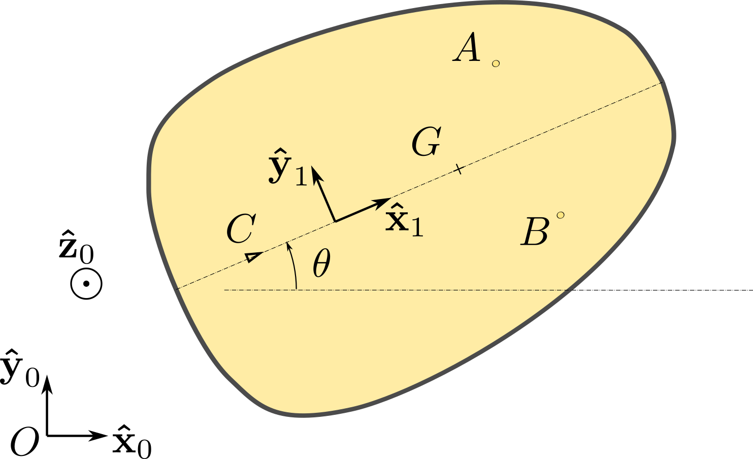
Consider the planar motion of a rigid body 1 of mass \(m\) supported by a horizontal plane \((O,\bx_0,\by_0)\) at points \(A\) and \(B\) due to the presence of legs which slide freely over the support, and at \(C\) due to a blade which constrains the direction of the motion. More specifically, the velocity \(\vel_{C\in 1/0}\) of \(C\) is always directed along unit vector \(\bx_1\) of the sleigh. The position of the body is specified by the horizontal coordinates, \(x\) and \(y\text{,}\) of the point of contact \(C\) and by the angle \(\theta\) that the axis \((C,\bx_1)\) fixed to the body makes with the axis \((O,\bx_0)\) fixed in referential 0. See Figure 13.4.7. Denote by \(G\) the mass center of the body located on line \((C,\bx_1)\text{,}\) by \(b\) the distance \(|CG|\) and by \(I_C\) the moment of inertia about axis \((C,\bz_0)\text{.}\) The joint at \(C\) is assumed frictionless.
Figure 13.4.7.
  1. Express the non-holonomic constraint equation in terms of \((\dx,\dy,\dte)\text{.}\)
  2. Express the conditions which guarantee that the joint at \(C\) is ideal.
  3. Derive the three Lagrange equations \(\cL_{1/0}^q\) for \(q=x,y,\te\text{.}\) Deduce the equations of motion of the body.
Solution.
a. We impose that the velocity of \(C\) is directed along \(\bx_1\) to find
\begin{equation*} \vel_{C\in 1/0} \cdot \by_1 = -\dx\sin\te +\dy \cos\te = 0 \qquad{(1)} \end{equation*}
Equation (1) represents a non-integrable non-holonomic constraint equation. The kinematic screw of body 1 takes the following expression in terms of coordinates \(x,y,\te\text{:}\)
\begin{equation*} \{\cV_{1/0} \}= \begin{Bmatrix} \dte \bz_0 \\\\ \dx \bx_0 + \dy \by_0 \end{Bmatrix}_C = \begin{Bmatrix} \dte \bz_0 \\\\ v_C \bx_1 \end{Bmatrix}_C \end{equation*}
with \(v_C\) given by \(v_C = \dx \cos\te + \dy \sin\te\text{.}\)
b. The action screw at contact point \(C\) must satisfy
\begin{equation*} \begin{Bmatrix} \dte \bz_0 \\\\ v_C \bx_1 \end{Bmatrix}_C \cdot \begin{Bmatrix} X\bx_0 +Y \by_0 +Z \bz_0 \\\\ L\bx_0 +M\by_0 +N \bz_0 \end{Bmatrix}_C = N \dte+ v_C (X \cos\te + Y \sin\te) =0 \end{equation*}
for all possible values of \(\dte\) and \(v_C\text{:}\) this leads to the conditions
\begin{equation*} N =0 , \qquad X\cos\te + Y \sin\te =0 \qquad{(2-3)} \end{equation*}
c.To derive the three Lagrange equations \(\cL_{1/0}^q\) for \(q=x,y,\te\text{,}\) we must assume Lagrange assumption that \((x,y,\te,\dx,\dy,\dte)\) are independent variables. We must ignore equation (1). Accordingly, the kinematic screw is written in the form
\begin{equation*} \{\cV_{1/0} \}= \begin{Bmatrix} \dte \bz_0 \\\\ \dx \bx_0 + \dy \by_0 \end{Bmatrix}_C = \dte \begin{Bmatrix} \bz_0 \\\\ \bze\end{Bmatrix}_C + \dx \begin{Bmatrix} \bze \\\\ \bx_0 \end{Bmatrix}_C + \dy \begin{Bmatrix} \bze \\\\ \by_0 \end{Bmatrix}_C \end{equation*}
leading to the expressions of the partial kinematic screws:
\begin{equation*} \{\cV_{1/0}^x \}= \begin{Bmatrix} \bze \\\\ \bx_0 \end{Bmatrix}_C , \quad \{\cV_{1/0}^y \}= \begin{Bmatrix} \bze \\\\ \by_0 \end{Bmatrix}_C , \quad \{\cV_{1/0}^\te \}= \begin{Bmatrix} \bz_0 \\\\ \bze\end{Bmatrix}_C \end{equation*}
and the expression of the kinetic energy (using equation (9.7.1))
\begin{align*} 2\kin_{1/0} \amp = m \vel_{C\in 1/0}^2 + 2m \vel_{C\in 1/0} \cdot (\dte\bz_0 \times b\bx_1) + I_C \dte^2\\ \amp = m (\dx^2 + \dy^2) + 2m b \dte (-\dx\sin\te + \dy \cos\te) + I_C \dte^2 \end{align*}
From this last expression, we obtain
\begin{equation*} \left[ \frac{d}{dt}\frac{\partial}{\partial \dx}-\frac{\partial}{\partial x}\right] \kin_{1/0} = m \frac{d}{dt} (\dx- b\dte \sin\te) \end{equation*}
\begin{equation*} \left[ \frac{d}{dt}\frac{\partial}{\partial \dy}-\frac{\partial}{\partial y}\right] \kin_{1/0} = m \frac{d}{dt} (\dy+ b\dte \cos\te) \end{equation*}
\begin{equation*} \left[ \frac{d}{dt}\frac{\partial}{\partial \dte}-\frac{\partial}{\partial \te}\right] \kin_{1/0} = \frac{d}{dt} (I_C \dte- mb\dx\sin\te+mb \dy\cos\te) - mb \dte(-\dx\cos\te-\dy\sin\te) \end{equation*}
The expressions of the power coefficients \(\qQ^q_{\bar{1}\to 1/0}\) are found as follows
\begin{equation*} \qQ^x_{\bar{1}\to 1/0}= \{\cV_{1/0}^x \}\cdot \begin{Bmatrix} X\bx_0 +Y \by_0 +Z \bz_0 \\\\ L\bx_0 +M\by_0 +N \bz_0 \end{Bmatrix}_C = X \end{equation*}
\begin{equation*} \qQ^y_{\bar{1}\to 1/0}= \{\cV_{1/0}^y \}\cdot \begin{Bmatrix} X\bx_0 +Y \by_0 +Z \bz_0 \\\\ L\bx_0 +M\by_0 +N \bz_0 \end{Bmatrix}_C = Y \end{equation*}
\begin{equation*} \qQ^\te_{\bar{1}\to 1/0}= \{\cV_{1/0}^\te \}\cdot \begin{Bmatrix} X\bx_0 +Y \by_0 +Z \bz_0 \\\\ L\bx_0 +M\by_0 +N \bz_0 \end{Bmatrix}_C = N \end{equation*}
The effect of gravity and the reactions at \(A\) and \(B\) do not contribute to these energy coefficients. These expressions lead to three Lagrange equations:
\begin{align*} \cL_{1/0}^x: \amp \quad m \frac{d}{dt} (\dx- b\dte \sin\te) = X \amp \qquad(4)\\ \cL_{1/0}^y:\amp \quad m \frac{d}{dt} (\dy+ b\dte \cos\te) = Y \amp \qquad (5)\\ \cL_{1/0}^\te: \amp \quad I_C \ddte + mb(-\ddx\sin\te+\ddy\cos\te) = N \amp \qquad (6) \end{align*}
Equations (1-6) allow for the determination of \((x,y,\te,X,Y,N)\text{.}\) By eliminating \((X,Y,N)\) we obtain the equations of motions after a few manipulations:
\begin{align*} \ddx \amp = b \dte^2 \cos\te - \dx\dte \tan\te\\ \ddy \amp = b \dte^2 \sin\te + \dx\dte\\ I_C \ddte \amp = -mb \dte (\dx\cos\te + \dy \sin\te) \end{align*}

Remark 13.4.8.

The incorrect way to proceed is to use the expressions
\begin{equation*} \{\cV_{1/0} \} = \begin{Bmatrix} \dte \bz_0 \\\\ (\dx \cos\te + \dy \sin\te) \bx_1 \end{Bmatrix}_C \end{equation*}
\begin{equation*} \{\cV_{1/0}^x \}= \begin{Bmatrix} \bze \\\\ \cos\te\bx_1 \end{Bmatrix}_C , \quad \{\cV_{1/0}^y \}= \begin{Bmatrix} \bze \\\\ \sin\te \bx_1\end{Bmatrix}_C , \quad \{\cV_{1/0}^\te \}= \begin{Bmatrix} \bz_0 \\\\ \bze\end{Bmatrix}_C \end{equation*}
since this clearly violates the requirement that \((x,y,\te,\dx,\dy,\dte)\) be independent variables. Similarly, the kinetic energy can be written as
\begin{equation*} 2\kin_{1/0} = m (\dx^2 + \dy^2) + I_C \dte^2 \end{equation*}
This expression is correct, but it cannot be used for the purpose of deriving Lagrange equations since, once again, the requirement that \((x,y,\te,\dx,\dy,\dte)\) be independent variables is not satisfied. Using these expressions one would find the erroneous equations
\begin{align*} \ddx \amp = \cos\te (X \cos\te + Y\sin\te) =0\\ \ddy \amp = \sin\te (X \cos\te + Y\sin\te)=0\\ I_C \ddte \amp = N=0 \end{align*}

Remark 13.4.9.

In Section 13.6, we will learn how to derive Lagrange equations by taking into account the non-holonomic constraint (1).