Section 11.3 Conservation Laws: First Integrals of Motion

Recall that a material system \(\Si\) admits a first integral of motion if it satisfies an equation of the type \(F(\dbq, \bq , t) = \text{constant}\) where \(\bq\) represents some set of coordinates associated with the motion of \(\Si\) relative to a (Newtonian) referential. A first integral of motion typically corresponds to a conservation law, such as conservation of linear momentum, angular momentum, energy, etc. Here, we examine general conditions leading to conservation of linear or angular momentum.

Subsection 11.3.1 Conservation of Linear Momentum

Let \(\Si\) be a material system of constant mass \(m\) and mass center \(G\text{.}\) Two cases can be stated for conservation of the linear momentum of \(\Si\) to arise.
  • Case 1: If the total resultant force acting on \(\Si\) satisfies \(\bF_{ \bSi \to \Si}= {\bf 0}\) at all time, then \(m {\bf a}_{G/ \cE}= {\bf 0}\) which implies
    \begin{equation} m \vel_{G / \cE} = \text{constant}\tag{11.3.1} \end{equation}
    This states the conservation of the linear momentum of \(\Sigma\) relative to \(\cE\text{.}\) Three first integrals of motion are obtained.
  • Case 2: If the total resultant force acting on \(\Si\) satisfies \(\bu \cdot \bF_{\bSi \to \Si} =0\) at all time, given a unit vector \(\bu\) constant in \(\cE\text{,}\) then we have
    \begin{equation} \bu \cdot m \vel_{G / \cE} = \text{constant}\tag{11.3.2} \end{equation}
    This states the conservation of linear momentum of \(\Sigma\) relative to \(\cE\) in the direction \(\bu\text{.}\) A single first integral of motion is obtained.
The following example illustrates conservation of linear momentum.

Example 11.3.1.

A pendulum is assembled by connecting a body 2 of mass center \(B\) and mass \(m\) to a slider 2 of mass center \(A\) and mass \(M\text{.}\) Slider 1 can translate without friction along the direction \(Ox\) of a referential 0 assumed Newtonian. Body 2 can rotate freely about a frictionless pivot at \(A\) relative to the slider. The motion of the system occurs in a vertical plane. The slider can be set in a initial position either sufficiently far from a vertical backstop or in contact with it. The pendulum is initially displaced at some angle \(-\pi / 2 \leq \te_0 \lt 0\text{,}\) defining positive angle \(\theta\) in the anticlockwise direction. The system slider/pendulum is then released without initial speed.
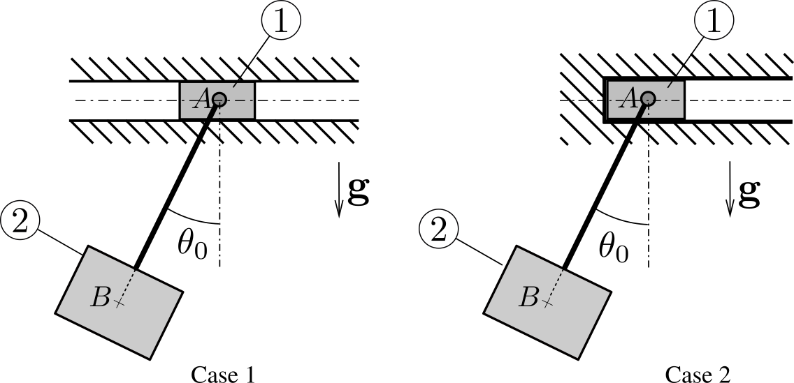
Figure 11.3.2.
Its position at any time \(t\) is defined by the coordinate \(x(t)\) of \(A\) measured along axis \(Ox\) and by the angle \(\te(t)\text{.}\) Denote by \(l\) the distance \(AB\) and by \(J =mk^2\) the moment of inertia of pendulum 2 about its axis of rotation.
  1. Case 1. The slider is set in a initial position sufficiently far from the backstop. Find the relationship between \(\dx\) and \(\dte\text{.}\) Describe the motion of the system. Describe the motion of the mass center \(G\) of the system. Along which curve does point \(B\) evolve? Find the period of the small amplitude oscillations of the system.
  2. Case 2. The slider is now set initially in contact with the backstop. Find the relationship between \(\dx\) and \(\dte\text{.}\) Show that initially the slider remains in contact with the backstop. When does this contact cease? Show that after contact ceases, the slider never comes back to the backstop. Carefully describe the motion of the system.
Solution.
  1. Case 1. Define the fixed unit vectors \((\be_x , \be_y , \be_z )\) with \(\be_x\) along horizontal axis \(Ox\text{,}\) \(\be_z\) vertical downward, and \(\be_y = \be_z \times \be_x\) perpendicular to the plane of motion. See Figure 11.3.3. The position of the system is defined by coordinate \(x(t)\) of \(A\) along axis \(Ox\) and by the oriented angle \(\te (t)\) which line \(AB\) makes with the vertical. Introduce unit vector \(\bu\) along line \(AB\) directed from \(A\) to \(B\text{,}\) and \(\bv = \be_y \times \bu\text{.}\) The position vectors of \(A\) and \(B\) are then given by
    \begin{equation*} \br_{OA} = x \be_x , \qquad \br_{OB} = x \be_x + l \bu. \end{equation*}
    Then the velocities of \(A\) and \(B\) are given by
    \begin{equation*} \vel_A = \dx \; \be_x , \qquad \vel_B = \dx \; \be_x + l \dte \bv . \end{equation*}
    At time \(t=0\text{,}\) we have \(\te = \te_0\text{,}\) and \(\dx = 0\) and \(\dte =0\) since the system is released without initial velocity.
    Figure 11.3.3.
    Denote by \(\Sigma\) the system slider/pendulum and by \(G\) its mass center. The external forces acting on \(\Sigma\) are the gravitational forces \(M \bg\) and \(m \bg\text{,}\) and the reaction force \(N \be_z \) directed along \(\be_z \) in the absence of friction. Hence, the resultant force \(\bF_{\bSi\to\Si}\) on \(\Sigma\) satisfies \(\bF_{\bSi\to\Si} \cdot \be_x =0\text{.}\) This implies that \((m+M) \ba_G \cdot \be_x =0\) and by integration that (\(\be_x\) is a constant unit vector)
    \begin{equation*} (m+M) \vel_G \cdot \be_x = \text{constant} = 0 \end{equation*}
    The constant of integration vanishes since the initial velocity of the system is zero. Hence, there is conservation of the linear momentum of \(\Sigma\) on axis \(Ox\). With \((M+m) \vel_G = M \vel_A + m \vel_B\text{,}\) we obtain
    \begin{equation*} ( M \vel_A + m \vel_B) \cdot \be_x = (M+m ) \dx + m l \dte \cos\te = 0 \qquad{(1)} \end{equation*}
    This equation shows that the sign of \(\dx\) (which gives the direction taken by the slider) is the sign of \((- \dte \cos\te)\text{.}\) Since we expect the angle \(\te\) to remain in the interval \(- \pi /2 \lt \te \lt \pi /2\text{,}\) we have \(\text{sign} (\dx) = - \text{sign}(\dte)\text{:}\) if the pendulum rotates in the clockwise direction \((\dte \lt 0)\text{,}\) then the slider moves forward \((\dx > 0)\text{.}\) Conversely, if it rotates in the counterclockwise direction \((\dte \gt 0)\text{,}\) then the slider moves backward \((\dx \lt 0)\text{.}\)
    The mass center \(G\) of the system moves along a vertical line since from equation (1) \(\vel_G \cdot \be_x =0\text{:}\) we get by integration \(\br_{OG} \cdot \be_x = \text{constant}\text{.}\) The position of \(B\) is given by \(\br_{OB}= (x + l \sin \te) \be_x + l \cos\te \be_z\text{,}\) where \(x = - { m \over m+M} l \sin\te\) by integration of (1) assuming \(x= 0\) when \(\te =0\text{.}\) The coordinates of \(B\) are then given by
    \begin{equation*} x_B = {M \over M+m} l \sin\te, \qquad z_B = l \cos\te \end{equation*}
    Eliminating \(\te\) gives the Cartesian equation of the trajectory of \(B\text{:}\)
    \begin{equation*} \left( {x_B \over l( 1 + {m\over M}) } \right)^2 + \left( {z_B \over l} \right)^2 = 1 \end{equation*}
    This equation is that of an ellipse.
    To find the period of small oscillations, we need a second equation: we apply the moment equation for pendulum 2 about point \(A\text{:}\)
    \begin{equation*} \be_y \cdot \bD_{A, 2/0} = \be_y \cdot \bM_{A, \bar{2}\to 2} = \be_y \cdot (\br_{AB} \times mg\be_z )= -mgl \sin\te \end{equation*}
    with \(\bD_{A, 2/0} = d\bH_{A, 2/0} /dt + \vel_A \times m\vel_G\) and \(\bH_{A , 2/0} \cdot\be_y = J \dte + \be_y \cdot (m \br_{AB}\times \vel_A) = J\dte + m l\dx\cos\te\text{.}\) This gives our second equation of motion
    \begin{equation*} J\ddte + ml \ddx \cos\te = -mgl \sin\te \qquad{(2)} \end{equation*}
    Assuming that the initial angle \(\te_0\) is small, the angle \(\te\) and its derivative \(\dte\) remain small at all time. Using the approximations \(\sin\te \approx \te\) and \(\cos\te\approx 1\text{,}\) we obtain a linear approximation of this equation
    \begin{equation*} \Big( k^2 - \frac{m}{m+M} l^2 \Big) \ddte + {gl} \te =0 \end{equation*}
    The period of the oscillations of the system is then
    \begin{equation*} T = 2\pi \sqrt{ \frac{gl}{k^2- \frac{m}{m+M} l^2 } } \end{equation*}
    Note that \(k\) is necessarily larger than \(l \sqrt{\frac{m}{m+M}}\text{.}\)
  2. Case 2.
    If the slider is initially in contact with the backstop, we can expect an initial phase during which it remains in contact with the backstop: indeed as the angle increases from the initial value \(\te_0 \lt 0\text{,}\) the slider has a tendency to move backward. Hence, we can assume that there exists an initial phase during which \(\dx = 0\) and the external force exerted to system \(\Sigma\) is augmented by a horizontal reaction \(R \bx\) due to the backstop. As long as \(R > 0\text{,}\) contact is maintained. If \(R (t) = 0\) at some time \(t_1\text{,}\) then the slider ceases to be in contact with the backstop. During the first phase, the motion of \(\Sigma\) along the \(x\)-axis is governed by the equation
    \begin{align*} R \amp = (m+M) \ba_G \cdot \be_x = {d\over dt} [ (m+M) \dx + ml \dte \cos\te ]\\ \amp = ml (\ddte \cos\te - \dte^2 \sin\te ) \end{align*}
    We can predict the sign of \(R\) without having to find the angular acceleration \(\ddte\) and the angular velocity \(\dte\) as a function of \(\te\text{.}\) Indeed the angular acceleration \(\ddte\) is positive (\(\dte\) increases) in the range \(\te_0 \leq \te \lt 0\text{,}\) becomes zero for \(\te = 0\text{,}\) and is negative for \(\te > 0\text{.}\) Hence \({\rm sign}(\ddte ) = - {\rm sign} (\sin\te)\text{.}\) This shows that
    \begin{equation*} \left\{ \begin{array}{lr} R \gt 0 , \amp \qquad \te_0 \leq \te \lt 0 \\ R = 0 , \amp \qquad \te = 0 \\ R \lt 0 , \amp \qquad \te \gt 0 \end{array} \right. \end{equation*}
    Hence the slider ceases to be in contact with the backstop the moment the pendulum crosses the vertical. The instant \(t_1\) at which this occurs is of course a function of the initial angle \(\te_0\text{.}\) In the second phase (\(t \geq t_1\)), once contact with the backstop ceases, we are in a similar situation as in case 1: there is conservation of linear momentum of \(\Sigma\) along axis \(Ox\text{.}\) In this case, however, the linear momentum of \(\Sigma\) along axis \(Ox\) is not zero since
    \begin{equation*} (m+M) \vel_{G} \cdot \be_x = {\rm constant} = m \vel_B (t_1) \cdot\be_x = m l \dte_1 \end{equation*}
    where the constant of the motion is obtained at time \(t=t_1\text{:}\) \(\dte = \dte_1\) and \(\dx =0\text{.}\) Hence in the second phase, the mass center of \(\Sigma\) moves uniformly in the direction of axis \(Ox\). Furthermore, the slider’s velocity \(\dx\) is given by
    \begin{equation*} \dx = {m \over M+m} l ( \dte_1 - \dte \cos\te ) \end{equation*}
    We expect in phase 2 that \(\dte \leq \dte_1\) and that \(\dte = \dte_1 > 0\) at \(\te =0\text{.}\) This shows that the slider velocity remains positive and becomes zero whenever the pendulum crosses the vertical with a positive velocity. Hence the slider always moves forward in a non-uniform way in the \(x\text{.}\)direction, coming to a stop whenever the pendulum crosses the vertical in the forward direction. It never comes back toward the backstop. The situation is thus quite different from that of case 1.
In the next section, we examine conditions under which angular momentum is conserved.

Subsection 11.3.2 Conservation of Angular Momentum

Let \(\Si\) be a material system of constant mass \(m\) and mass center \(G\text{.}\) Two cases can be stated for conservation of the angular momentum of \(\Si\) to arise.
  • Case 1: If the total external moment about point \(A\) satisfies \({\bf M}_{A,\bSi \to \Si} = {\bf 0}\) at all time, where \(A\) is a fixed point of \(\cE\) or the mass center \(G\) of system \(\Si\text{,}\) then this implies \(\bD_{A, \Sigma / \cE} = {\bf 0}\text{,}\) leading to
    \begin{equation} \bH_{A, \Sigma / \cE} = \text{constant}\tag{11.3.3} \end{equation}
    This states the conservation of the angular momentum about \(A\) of \(\Sigma\) relative to \(\cE\). Three first integrals of motion are obtained.
  • Case 2: If the total external moment about fixed point \(A\) satisfies \(\bu \cdot {\bf M}_{A,\bSi \to \Si} = 0\text{,}\) given a constant vector \(\bu\) of \(\cE\text{,}\) then we have
    \begin{equation} \bu \cdot \bH_{A, \Sigma / \cE} = \text{constant}\tag{11.3.4} \end{equation}
    This states the conservation of the angular momentum about \(A\) of \(\Sigma\) relative to \(\cE\) in the direction \(\bu\text{.}\) A single first integral of motion is obtained. Note that if \(\bu\) is not a constant vector, then in general the condition \(\bu \cdot \bM_{A, \bSi \to \Si} = 0\) does not imply that \(\bu \cdot \bH_{A, \Sigma / \cE} = \text{constant}\text{.}\)
The following examples illustrate conservation of angular momentum.

Example 11.3.4.

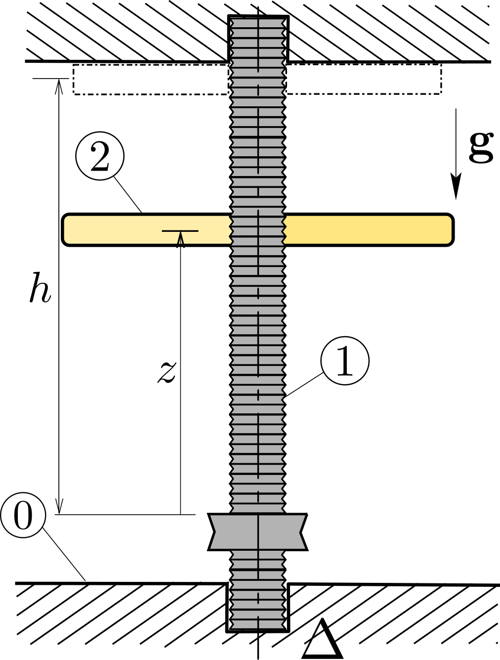
Consider a system \(\Sigma\) of two rigid bodies 1 and 2. Body 1 (of moment of inertia \(J_1\) about \(\Delta\text{.}\) is free to rotate without friction about a vertical axis \(\Delta\) of referential 0. A uniform disk 2 (of mass \(m_2\) and moment of inertia \(J_2\) about \(\Delta\)) is constrained to 1 by a frictionless helical joint of axis \(\Delta\) and constant pitch \(p\) (when body 2 rotates by angle \(2\pi\) about \(\Delta\text{,}\) it translates by a distance \(p\) relative to body 1). The system is initially at rest. Upon release, body 2 travels downward until it reaches the end of the screw at a distance \(h\) from its initial position. At this point the two bodies are locked together. See Figure 11.3.5.
Figure 11.3.5.
  1. Find the angular velocities \(\bom_{1/0}\) and \(\bom_{2/0}\) of the two bodies just before body 2 hits the end of the screw, in terms of parameters \(h\text{,}\) \(m_2\text{,}\) \(J_1\) and \(J_2\text{.}\)
  2. Find the same quantities after body 2 hits the end of the screw.
Solution.
a. Denote axis \(\Delta = (O, \bz_0)\text{,}\) \(\bz_0\) being directed upward. First consider the kinematics of the problem. The release of body 2 sets both 1 and 2 in rotation about \(\Delta\text{.}\) Denote \(\bom_{1/0} = \om_1 \bz_0\) and \(\bom_{2/0} = \om_2 \bz_0\text{.}\) The helical joint between 2 and 1 and the pivot joint between 1 and 0 imposes the following kinematic screws
\begin{equation*} \{ \cV_{2/1} \} = \left\{ \begin{array}{c} (\om_2 -\om_1) \bz_0 \\ {p \over 2\pi} (\om_2 -\om_1) \bz_0 \end{array} \right\} _{G_2}, \qquad \{ \cV_{1/0} \} = \left\{ \begin{array}{c} \om_1 \bz_0 \\ \bze \end{array} \right\} _{P\in\Delta}, \end{equation*}
where \(G_2\) is the mass center of body 2 (located on axis \(\Delta\)). This leads to
\begin{equation*} \vel_{G_2 /0} = \vel_{G_2 \in 2/1}+ \vel_{G_2 \in 1/0} = {p \over 2\pi} (\om_2 -\om_1) \bz_0 \qquad{(1)} \end{equation*}
Consider the external actions exerted on system \(\Si\text{:}\) the gravitational forces \(\{\cA_{\text{Earth}\to \Si}\}^g\) and the contact actions \(\{\cA_{ 0 \to 1 }^c\}\) acting through pivot: both actions have zero moment about axis \(\Delta\text{,}\) that is, \(\bz_0 \cdot \bM_{O, \bSi\to \Si} = 0\text{.}\) This leads to \(\bz_0 \cdot (\bH_{O, 1/0} + \bH_{O, 2/0} ) =0\text{,}\) or
\begin{equation*} J_1 \om_1 + J_2 \om_2 =0. \qquad{(2)} \end{equation*}
Then consider the external actions exerted on body 2: the gravitational forces \(\{\cA_{\text{Earth}\to 2}^g\}\) and the contact actions \(\{\cA_{1 \to 2}^c\}\text{.}\) Since the helical joint is frictionless, we have
\begin{equation*} {p\over 2\pi} \bR^c_{1 \to 2} \cdot \bz_0 + \bM^c_{O, 1 \to 2} \cdot \bz_0 = 0 \qquad{(3)} \end{equation*}
To account for this relationship, we first write the FTD applied to body 2
\begin{equation*} -m_2 g \bz_0 + \bR^c_{1 \to 2} = m_2 \ba_{G_2 /0} , \qquad \bM^c_{O, 1 \to 2} = \bD_{O, 2/0} \qquad{(4-5)} \end{equation*}
Equation (3) then leads to
\begin{equation*} {p\over 2\pi} \left(m_2 g + m_2 {p \over 2\pi} (\dom_2 -\dom_1) \right) + J_2 \dom_2 =0 \end{equation*}
This last equation can be integrated to give
\begin{equation*} {p \over 2\pi} m_2 g t + m_2 ({p \over 2\pi})^2 (\om_2 -\om_1) + J_2 \om_2 =0 \end{equation*}
using \(\om_1 = \om_2 =0\) at \(t=0\text{.}\) Using equation (1) we can find the time \(t_*\) taken by \(G_2\) to travel distance \(h\text{:}\)
\begin{equation*} h = ({p \over 2\pi})^2 (1+ J_2/J_1) { m_2 g t_*^2 /2 \over m_2 ({p \over 2\pi})^2 (1+ J_2/J_1) + J_2} \end{equation*}
leading to final value of angular velocity \(\om_2\)
\begin{equation*} \omega_{2,*}^2 = {1\over 1+J_2/J_1} {2m_2 gh \over m_2 ({p \over 2\pi})^2 (1+ J_2/J_1) + J_2} \end{equation*}
b. After body 2 hits the end of the screw, both bodies 1 and 2 rotate about \(\Delta\) at the same angular velocity \(\om_1 = \om_2 = \om_{**}\text{.}\) The angular momentum of the system is still conserved \(J_1 \om_1 + J_2 \om_2 =0\text{.}\) Hence \(\om_{**}=0\text{.}\)

Example 11.3.6.

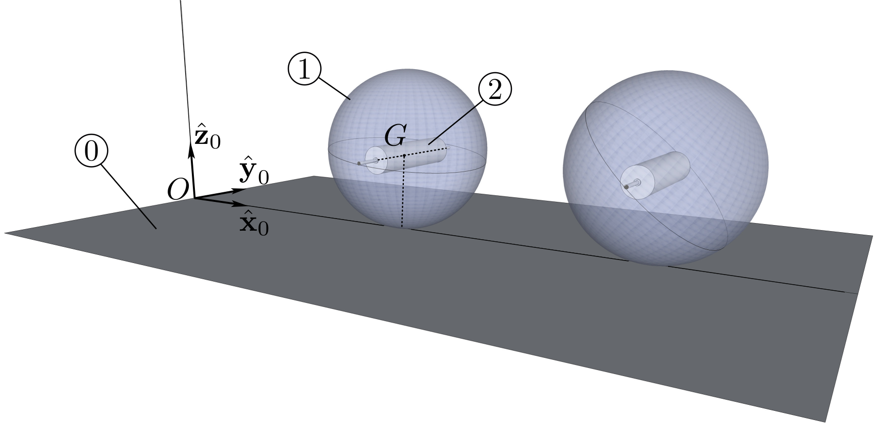
Figure 11.3.7 shows a spherical shell 1 (of mass center \(G\text{,}\) mass \(m_1\text{,}\) and radius \(R\)) in contact with a rough horizontal plane \((O, \bx_0 , \by_0)\) of a referential 0 assumed Newtonian. A cylinder 2 (of mass \(m_2\text{,}\) radius \(R\)) is connected in the interior of 1 by a pivot whose axis coincides with the diameter \((G,\by_0)\) of 1. The mass center of 2 coincides with point \(G\text{.}\) At \(t=0\text{,}\) body 1 is immobile, while body 2 is given an initial angular velocity \(\bom_{2/0}= \om_0 \by_0\) with \(\om_0 >0\text{.}\) The effect of friction on the connection between 1 and 2 induces the constant couple \(- \cC \by_0\) so as to oppose the rotation of 2 relative to 1. Denote by \(I_1\) and \(I_2\) the moments of inertia of bodies 1 and 2 about axis \((G, \by_0)\text{.}\)
Figure 11.3.7.
  1. Sphere 1 is observed to roll forward along line \((O, \bx_0)\text{.}\) Explain how this is so. Assuming rolling without slipping of 1, find an equation which relates angular velocity \(\bom_{1/0} = \om_1 \by_0\) to angular velocity \(\bom_{2/0}= \om_2 \by_0\text{.}\)
  2. Find another equation which gives \(\om_2\) versus time. Using these two equations, find \(\om_2\) and \(\om_1\) versus time, and deduce the time \(T\) taken for the relative rotation between 2 and 1 to cease. Describe the motion of the system for \(t> T\text{.}\)
Solution.
a. This can be explained by conservation of angular momentum. To find out exactly how this takes place, we write the expression of external action screw exerted on the system \(\Si =\){1,2}:
\begin{equation*} \{ \cA_{\bSi\to\Si} \} = \left\{ \begin{array}{c} \bR_I \\ \bze \end{array} \right\}_I + \left\{ \begin{array}{c} - (m_1 + m_2) g\bz_0 \\ \bze \end{array} \right\}_G = \left\{ \begin{array}{c} \bR_I - (m_1 + m_2) g\bz_0 \\ \bze \end{array} \right\}_I \end{equation*}
This shows that \(\bM_{I ,\bSi\to\Si} = \bze\) implying that \(\bD_{I, \Si /0} = \bze\text{.}\) Now the dynamic moment of system \(\Si\) about \(I\) is found to be
\begin{align*} \bD_{I, \Si /0} \amp = {d\over dt} ( \bH_{I, 1/0} + \bH_{I, 2/0} ) + \vel_{I/0}\times m_1 \vel_{G/0} +\vel_{I/0}\times m_2 \vel_{G/0}\\ \amp = {d\over dt} ( \bH_{I, 1/0} + \bH_{I, 2/0} ) \end{align*}
where we have used \(\vel_{I/0}= \vel_{G/0}\text{.}\) This leads to conservation of angular momentum \(\bH_{I, 1/0} + \bH_{I, 2/0}\text{.:}\) we find
\begin{equation*} \bH_{I, 1/0} = (I_1 + m_1 R^2) \om_1 \by_0 , \quad \bH_{I, 2/0} = (I_2\om_2 + m_2 R^2 \om_1 ) \by_0 \end{equation*}
where these expressions can be obtained by using
\begin{equation*} \bH_{I, i/0} = \bH_{C , i/0} + \br_{IG}\times m_i \vel_{G/0} \end{equation*}
with \(\vel_{G/0} = R\om_1 \bx_0\) (by accounting for no-slip condition at \(I\)). Hence we obtain, using \(\om_1 =0\) and \(\om_2 = \om_0\) at \(t=0\text{:}\)
\begin{equation*} (I_1 +MR^2) \om_1 + I_2 \om_2 = {\rm constant} = I_2 \om_0 \end{equation*}
leading to
\begin{equation*} (I_1 +MR^2)\om_1 = I_2 (\om_0 - \om_2) \end{equation*}
where we have denoted \(M = m_1 + m_2\text{.}\)
We expect that \(\om_2 (t) \lt \om_0\) due to slowing effect of the frictional couple between 1 and 2. This shows that \(\om_1 > 0\text{:}\) the sphere rolls forward along axis \((O,\bx_0)\text{.}\)
b. To find a second equation, we write the dynamic moment equation which gives the rate of change of angular momentum \(\bH_{G, 2/0}\) of body 2 about \(G\text{:}\)
\begin{equation*} {d\over dt} \bH_{G, 2/0} = \bM_{G, 1\to 2}^c + \bM_{G, \bar{2}\to 2}^g = -\cC \by_0 \end{equation*}
leading to \(I_2 \dot{\om}_2 = -\cC\) which can be integrated to give
\begin{equation*} \om_2 (t) = \om_0 - \frac{\cC t}{ I_2}, \qquad \om_1 = \frac{\cC t}{I_1 + MR^2} \end{equation*}
At time \(t=T\text{,}\) the relative motion of 2 has stopped so that \(\om_2 = \om_1\text{:}\) this gives time \(T\)
\begin{equation*} T = \frac{\om_0}{\cC}\frac{I_2(I_1 + MR^2)}{I_1+I_2+MR^2} \end{equation*}
Note that if \(I_2 \ll I_1\text{,}\) we find \(T\approx 0\) as expected. For \(t>T\text{,}\) the sphere rolls uniformly at constant angular velocity \(\om_2 (T)\text{.}\)
The following example shows that in some circumstances the angular momentum of a rigid body relative to a particular Newtonian referential can be conserved along a direction which is not fixed relative to this referential.

Example 11.3.8.

Two bodies 1 and 2 are in motion relative to a referential 0 attached to Earth. Bodies 1 and 2 are connected by a frictionless pivot of axis \((G_2, \bz_2)\text{,}\) where \(G_2\) is the mass center of body 2. Assume that body 2 is an axisymmetric rigid body about \((G_2, \bz_2)\text{.}\) Assume that on a basis \(b_2 (\bx_2,\by_2,\bz_2)\) attached to 2, the inertia operator of 2 takes the form
\begin{equation*} [\cI_{G_2, 2}]_{b_2} = \begin{bmatrix} A_2 \amp 0 \amp 0 \\ 0 \amp A_2 \amp 0 \\ 0 \amp 0 \amp C_2 \\ \end{bmatrix} _{b_2} \end{equation*}
The motion of body 1 relative to referential 0 is arbitrary. Assume that there are no other mechanical actions exerted on body 2 other than Earth’s gravity. Show that the angular momentum of 2 about \(G_2\) is conserved along axis \(\bz_2\text{:}\)
\begin{equation*} \bz_2 \cdot \bH_{G_2, 2 /0} = \text{constant} \end{equation*}
Figure 11.3.9.
Solution.
Since \(G_2\) is the mass center of body 22, we have \(\bM_{G_2 , \bar{2} \to 2}^g = \bze\text{.}\) The frictionless pivot implies \(\bz_2 \cdot \bM_{G_2 , \bar{2} \to 2} = \bze\text{.}\) This leads to
\begin{equation*} \bz_2 \cdot \frac{d}{dt} \bH _{G_2 , 2/0} = 0 \end{equation*}
This can be written in the following form
\begin{equation*} \frac{d}{dt} [\bz_2 \cdot \bH _{G_2 , 2/0}] - \bH _{G_2 , 2/0} \cdot \frac{d\bz_2}{dt} =0 \end{equation*}
To evaluate the expression \(\bH _{G_2 , 2/0} \cdot d\bz_2 /dt\) we first express angular velocity \(\bom_{2/0}\) on basis \(b_2 (\bx_2,\by_2,\bz_2)\text{:}\)
\begin{equation*} \bom_{2/0} = p_2 \bx_2 + q_2 \by_2+ r_2 \bz_2 \end{equation*}
Then we have
\begin{equation*} \frac{d\bz_2}{dt} = \bom_{2/0} \times \bz_2 = (p_2 \bx_2 + q_2 \by_2+ r_2 \bz_2) \times \bz_2 = - p_2 \by_2 + q_2 \bx_2 \end{equation*}
and
\begin{equation*} \bH _{G_2 , 2/0} = \cI_{G_2, 2}(\bom_{2/0}) = A_2 p_2 \bx_2 + A_2 q_2 \by_2 + C_2 r_2 \bz_2 \end{equation*}
This shows that
\begin{equation*} \bH _{G_2 , 2/0} \cdot \frac{d\bz_2}{dt} = (A_2 p_2 \bx_2 + A_2 q_2 \by_2 + C_2 r_2 \bz_2 ) \cdot (- p_2 \by_2 + q_2 \bx_2) = 0 \end{equation*}
leading to
\begin{equation*} \frac{d}{dt} [\bz_2 \cdot \bH _{G_2 , 2/0}] = 0 \end{equation*}
or
\begin{equation*} \bz_2 \cdot \bH _{G_2 , 2/0} = \text{constant} \end{equation*}
This shows that the angular momentum about \(G_2\) of body 2 relative to 0 in the direction \(\bz_2\) is conserved.