Section 9.9 Examples

Example 9.9.1.

A rigid body 1 is constrained to rotate about a fixed axis \((O,\bz_0)\) of a referential 0. Body 1 is in the shape of a rectangular plate (of negligible thickness) of uniform mass \(m\text{,}\) with \(\br_{OB} = 2b \bz_0\) and \(\br_{OA} = 2a \bx_1\text{.}\) See Figure 9.9.2.
  1. Determine the inertia operator \(\cI_O\) about point \(O\text{.}\)
  2. Determine the kinetic \(\{ \cH _{1 / 0} \}\) and dynamic \(\{ \cD _{1/0} \}\) screws resolved about point \(O\) in terms of \(a\text{,}\) \(b\text{,}\) \(\te\) and its time-derivatives.
  3. Determine the kinetic energy \(\kin_{1/0}\text{.}\)
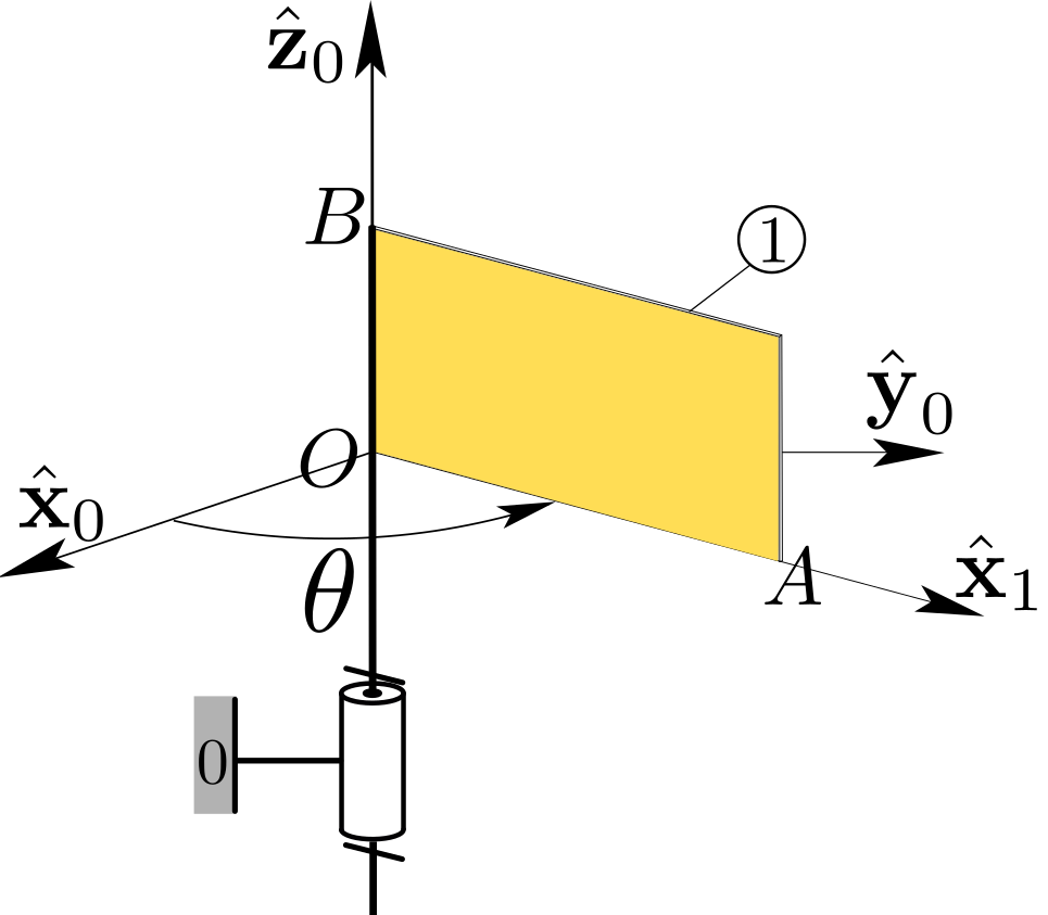
Figure 9.9.2.
Solution.
  1. The position of mass center \(G\) is defined on Cartesian axes \((O, \bx_1, \by_1=\bz_0\times\bx_1, \bz_0)\) attached to body 1 by the vector \(\br_{OG}= a\bx_1 +b\bz_0\text{.}\)
    We may find a representation of \(\cI_{O}\) on basis \(b_1 (\bx_1 , \by_1, \bz_0)\) (with \(\by_1 = \bz_0 \times \bx_1\)). On this basis the inertia matrix takes the form
    \begin{equation*} [\cI_O]_{b_1} = \begin{bmatrix} I_{Ox} \amp 0 \amp I_{Oxz} \\ 0 \amp I_{Oy} \amp 0 \\ I_{Oxz} \amp 0 \amp I_{Oz} \end{bmatrix}_{b_1} \end{equation*}
    where \(I_{Ox} = \int z^2 dm\text{,}\) \(I_{Oz} = \int x^2 dm\text{,}\) \(I_{Oy}= I_{Ox}+ I_{Oz}\text{,}\) and \(I_{Oxz} = -\int xz dm\text{.}\) Here \((x,z)\) represent the Cartesian coordinates of a generic point \(P\) of body 1 relative to axes \((O,\bx_1,\bz_0)\text{.}\)
    The values of \(I_{Ox}\text{,}\) \(I_{Oz}\text{,}\) and \(I_{Oxz}\) are found by a straightfoward application of the parallel axis theorem (the corresponding values about mass center \(G\) can be found in Section B.1):
    \begin{equation*} I_{Ox} =\tfrac{4}{3}m {b^2}, \quad I_{Oz} =\tfrac{4}{3} m {a^2}, \quad I_{Oxz}= -mab \end{equation*}
  2. First we find the angular momentum about \(O\) by applying formula (9.6.1)
    \begin{equation*} \bH_{O} = \cI_{O} (\bom) = \dte ( I_{Oxz} \bx_1 + I_{Oz} \bz_0) = m a \dte ( -b \bx_1 + \tfrac{4}{3}a \bz_0) \end{equation*}
    This gives the kinetic screw in the following form, using the expression of the linear momentum \(m a \dte \by_1\text{:}\)
    \begin{equation*} \{ {\cal H} _{1 / 0 } \} =\begin{Bmatrix} m a \dte \by_1 \\ \quad\\ m a \dte ( -b \bx_1 + \tfrac{4}{3} a \bz_0) \end{Bmatrix}_O \end{equation*}
    Next, we find the dynamic moment about about \(O\text{:}\) we use (9.3.4) (choosing point \(O\) for point \(A\)):
    \begin{equation*} \bD_O = \frac{d\bH_{O}}{dt} = m a \ddte ( -b \bx_1 + \tfrac{4}{3}a \bz_0) - m ab \dte^2 \by_1 \end{equation*}
    leading to the expression
    \begin{equation*} \{ {\cal D} _{1 / 0 } \} = \begin{Bmatrix} m a (\ddte \by_1 - \dte^2 \bx_1) \\\quad\\ m a ( -b\ddte \bx_1 -b \dte^2 \by_1 + \tfrac{4}{3} a\ddte \bz_0) \end{Bmatrix}_O \end{equation*}
  3. According to formula (9.7.1) (choosing point \(O\) for point \(B\)), the kinetic energy of body 1 is found to be
    \begin{equation*} \kin_{1/0} = \half \bom \cdot \cI_O (\bom) = \tfrac{2}{3} m {a^2}\dte^2 \end{equation*}
Example 9.9.3.

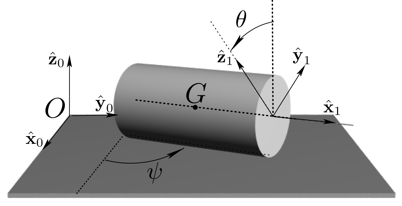
Figure 9.9.4 shows a rigid body 1 \((G, \bx_1, \by_1, \bz_1)\) in motion relative to a referential 0\((O, {\bx_0}, {\by_0}, {\bz_0})\text{.}\) Body 1 is an homogeneous cylinder, of mass \(m\text{,}\) radius \(R\text{,}\) length \(2l\text{,}\) mass center \(G\text{,}\) and axis \((G, \, {\bx}_1)\text{.}\) It is constrained to roll and pivot on the horizontal plane \((O,{\bx_0}, {\by_0})\text{.}\) The coordinates defining its position relative to 0 are \(x\text{,}\) \(y\text{,}\) \(\psi\text{,}\) and \(\theta\) such that:
\begin{equation*} {\bf r}_{OG} = x \, {\bx}_0 + y \, {\by}_0 +R \bz_0 , \,\, \psi = ({\bx_0} , {\bx_1}) , \,\, \theta = ({\bz_0} , {\bz_1}) . \end{equation*}
The inertia matrix of 1 about \(G\) takes the following form:
\begin{equation*} [\cI_G]_b = \begin{bmatrix} {m\over 2} R^{2} \amp 0 \amp 0 \\ 0 \amp {m\over 4} R^{2} + {m\over 3} l^{2} \amp 0 \\ 0 \amp 0 \amp {m\over 4} R^{2} + {m\over 3} l^{2} \\ \end{bmatrix} _b \end{equation*}
on any orthonormal basis \(b ({\bx_1}, - , - )\text{.}\)
Figure 9.9.4.
Determine
  1. the kinematic screw \(\{ {\cal V} _{1 / 0} \}\text{,}\)
  2. the kinetic screw \(\{ {\cal H} _{1 /0} \}\text{,}\)
  3. the dynamic \(\{ {\cal D} _{1 /0} \}\) screw,
  4. the kinetic energy \(\kin_{ 1 /0}\)
of body 1 relative to 0 in terms of the chosen coordinates, and their derivatives.
Solution.
  1. We first introduce unit vector \(\bv = \bz_0 \times \bx_1\) associated with rotation of angle \(\psi\) about \(\bz_0\text{.}\) Then the kinematics of body 1 relative to 0 is defined by \(\bom_{1/0} = \dpsi \bz_0 + \dte \bx_1\) and \(\vel_{G/0} = \dx \bx_0 + \dy \by_0\) leading to the following expression of \(\{ {\cal V} _{1 / 0} \}\)
    \begin{equation*} \{ {\cal V} _{1 / 0} \} = \left\{ \begin{array}{c} \dpsi \bz_0 + \dte \bx_1 \\ \dx \bx_0 + \dy \by_0 \end{array} \right\}_G \end{equation*}
  2. The angular momentum about \(G\) is found from the expression of \([\cI_G]_b\) on basis \(b = (\bx_1 , \bv, \bz_0)\text{:}\)
    \begin{align*} \bH_G \amp = \cI_G (\bom) = m \begin{bmatrix} \frac{R^2}{2} \amp 0 \amp 0 \\ 0 \amp \frac{R^2}{4} + \frac{l^2}{3} \amp 0 \\ 0 \amp 0 \amp \frac{R^2}{4} + \frac{l^2}{3} \\ \end{bmatrix}_b \begin{bmatrix} \dte \\ 0 \\ \dpsi \end{bmatrix}_b\\ \amp = \frac{m}{2} R^{2}\dte \bx_1 + (\frac{m}{4} R^{2} + \frac{m}{3} l^2) \dpsi \bz_0 \end{align*}
    leading to the expression of the kinetic screw of body 1:
    \begin{equation*} \{ {\cal H}_{1 /0} \} = \left\{ \begin{array}{c} m (\dx \bx_0 + \dy \by_0) \\ \quad\\ {m\over 2} R^{2}\dte \bx_1 + ({m\over 4} R^{2} + {m\over 3} l^2) \dpsi \bz_0 \end{array} \right\}_G \end{equation*}
  3. The dynamic moment about \(G\) is found by taking the time derivative of angular momentum \(\bH_G\text{:}\)
    \begin{equation*} \bD_G = \frac{d}{dt} \bH_G = {m\over 2} R^{2}\ddte \bx_1 + {m\over 2} R^{2}\dte\dpsi \bv + ({m\over 4} R^{2} + {m\over 3} l^2) \ddpsi \bz_0 \end{equation*}
    leading to the expression of the dynamic screw of body 1:
    \begin{equation*} \{ {\cal D}_{1 /0} \} = \left\{ \begin{array}{c} m (\ddx \bx_0 + \ddy \by_0) \\ \quad\\ {m\over 2} R^{2}\ddte \bx_1 +{m\over 2} R^{2}\dte\dpsi \bv + ({m\over 4} R^{2} + {m\over 3} l^2) \ddpsi \bz_0 \end{array} \right\}_G \end{equation*}
  4. Finally, the kinetic energy \(\kin_{1/0}\) is found according to
    \begin{align*} \kin_{1/0} \amp = \half m \vel_G^2 + \bom\cdot \cI_G (\bom)\\ \amp = \half m (\dx^2 + \dy^2) + \frac{m}{4} R^2 \dte^2 + \frac{m}{2}(\frac{R^2}{4} + \frac{l^2}{3}) \dpsi^2 \end{align*}

Example 9.9.5.

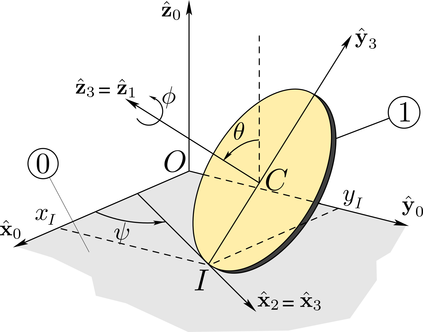
Consider the circular disk 1 of Example 7.3.11. Its mass center is \(C\text{,}\) its radius \(R\) and mass \(m\text{.}\) It is in motion on a planar support \((O,\, \bx_{0},\by_{0})\) of a referential 0\((O,\, \bx_{0},\by_{0},\bz_{0})\text{.}\) The unit vectors \((\bx_{3},\by_{3},\bz_{3})\) shown in Figure 9.9.6 are defined as follows:
  1. the line \((I, \, \bx_3)\) is the tangent at the point of contact \(I\) to the rim of the disk,
  2. the line \((I, \, \by_3)\) is the line connecting \(I\) and \(C\text{,}\)
  3. the line \((C, \, \bz_{3})\) is normal to the plane which contains the disk. The orientation of basis \((\bx_{3},\by_{3},\bz_{3})\) relative to \((\bx_{0},\by_{0},\bz_{0})\) is defined by the angles \(\psi =(\bx_0,\bx_3)\) and \(\te =(\bz_0, \bz_3)\text{.}\) Finally, the orientation of a basis of the disk relative to basis \((\bx_{3},\by_{3},\bz_{3})\) is characterized by the angle \(\phi\text{.}\)
The rolling and spinning of the disk on plane \((O,\, \bx_0,\by_0)\) is assumed to take place without slip at point \(I\text{.}\)
Figure 9.9.6.
  1. Using the results of Example 7.3.11, recall the expression of kinematic screw \(\{ \cV_{1 /0} \}\) resolved at point \(I\) in terms of components \(\om_{1}\text{,}\) \(\om_{2}\text{,}\) and \(\om_{3}\) of angular velocity \(\bom_{1/0}\) on basis \((\bx_{3},\by_{3},\bz_{3})\text{.}\) Express \((\om_1,\om_2,\om_3)\) in terms of \((\dpsi,\dte,\dphi)\text{.}\)
  2. Determine the kinetic screw \(\{\cH _{1 /0} \}\) resolved at point \(I\) in terms of components \(\om_{1}\text{,}\) \(\om_{2}\text{,}\) and \(\om_{3}\) (and their time-derivatives) of angular velocity \(\bom_{1/0}\) on basis \((\bx_{3},\by_{3},\bz_{3})\text{.}\)
  3. Repeat the work of question a) for the dynamic screw \(\{ \cD_{1 / 0} \}\text{.}\)
  4. Determine the kinetic energy \(\kin_{1/0}\text{.}\)
Solution.
  1. The angles \((\psi , \te, \phi)\) define the orientation of basis of body 1 relative to 0, giving \(\bom \equiv \bom_{1 /0} = \dpsi \bz_{0} + \dte \bx_{3}+ \dphi \bz_{3}\text{.}\) If we denote by \((\om_1 , \om_2 , \om_3 )\) the components of \(\bom\) on basis \(b_3 (\bx_{3},\by_{3},\bz_{3})\) , we find
    \begin{equation*} \om_{1} = \dte , \quad \om_{2} = \dpsi \sin\te , \quad \om_{3} = \dpsi \cos\te + \dphi \end{equation*}
    Given the non-holonomic constraints imposed by setting \(\vel_{I\in 1/0} =\bze\text{,}\) the motion of the disk is entirely specified in terms of three independent angles \((\psi , \te, \phi)\text{.}\) The kinematic screw of the disk can then be resolved at point \(I\) as follows
    \begin{equation*} \{ {\cal V} _{1 /0 } \} = \begin{Bmatrix} \om_{1} \bx_3 + \om_{2} \by_3 + \om_{3} \bz_3 \\ \quad\\ \bze \end{Bmatrix}_I \end{equation*}
  2. To express the kinetic screw at point \(I\) we need the angular momentum about \(I\text{.}\) We use formula (9.6.1) (with \(A\equiv I\) and \(B \equiv I\)):
    \begin{equation*} \bH_{I} = m \br_{IC} \times \vel_{I\in 1/0} + \cI_{I} (\bom) =\cI_{I} (\bom) \end{equation*}
    where we have taken into account the no-slip condition \(\vel_{I\in 1/0} = \bze\text{.}\) We need to find the inertia operator about \(I\text{.}\) We start with the expression of inertia matrix about \(C\) on basis \(b_3 (\bx_{3},\by_{3},\bz_{3})\)
    \begin{equation*} [\cI_{C}]_{b_3} = mR^2 \begin{bmatrix} {1\over 4} \amp 0 \amp 0 \\ 0 \amp {1\over 4} \amp 0 \\ 0 \amp 0 \amp {1\over 2} \end{bmatrix}_{b_3} \end{equation*}
    Note that basis \(b_3\) is not attached to the disk. However, the axisymmetry of the disk implies that \(I_\Delta ={1\over 4}mR^2\) for any line \(\Delta\) of the plane of the disk passing through \(C\text{.}\) We can then obtain the inertia matrix about \(I\) from that about \(C\) from the Parallel Axis Theorem:
    \begin{align*} [\cI_{I}]_{b_3} \amp = mR^2 \begin{bmatrix} {1\over 4} \amp 0 \amp 0 \\ 0 \amp {1\over 4} \amp 0 \\ 0 \amp 0 \amp {1\over 2} \end{bmatrix}_{b_3} + mR^2\begin{bmatrix} 1 \amp 0 \amp 0 \\ 0 \amp 0 \amp 0 \\ 0 \amp 0 \amp 1 \end{bmatrix} _{b_3}\\ \amp = mR^2 \begin{bmatrix} {5\over 4} \amp 0 \amp 0 \\ 0 \amp {1\over 4} \amp 0 \\ 0 \amp 0 \amp {3\over 2} \end{bmatrix}_{b_3} \end{align*}
    Now we can determine \(\bH_{I}\text{:}\)
    \begin{align*} \bH_{I} \amp = mR^2 \begin{bmatrix} {5\over 4} \amp 0 \amp 0 \\ 0 \amp {1\over 4} \amp 0 \\ 0 \amp 0 \amp {3\over 2} \end{bmatrix}_{b_3} \begin{bmatrix} \om_1 \\ \om_2 \\ \om_3 \end{bmatrix}_{b_3} = {1\over 4} mR^2 (5 \om_1 \bx_3 + \om_2 \by_3 +6\om_3 \bz_3) \end{align*}
    The kinetic screw can then be expressed in the following form
    \begin{equation*} \{ {\cal H} _{\cB / \cE } \} =\begin{Bmatrix} mR (\om_1 \bz_3 - \om_3 \bx_3) \\ \quad\\ {1\over 4} mR^2 (5 \om_1 \bx_3 + \om_2 \by_3 +6\om_3 \bz_3) \end{Bmatrix}_I \end{equation*}
    where the linear momentum of the disk has been found as \(m\vel_C = m \bom\times\br_{IC}\text{.}\) An alternative method to find \(\bH_I\) is to relate it to \(\bH_C\) by the equation:
    \begin{equation*} \bH_I = \bH_C + \br_{IC}\times m\vel_C \end{equation*}
    using
    \begin{equation*} \bH_C = \cI_{C} \bom = {1\over 4} mR^2 (\om_1 \bx_3 + \om_2 \by_3 +2\om_3 \bz_3) \end{equation*}
    The same result would be found.
  3. Next, we need the dynamic moment about \(I\text{:}\) we use (9.3.4) (with \(B\equiv I\))
    \begin{equation*} \bD_{I} = {d \over dt}\bH_{I} + \vel_{I} \times m \vel_{C} \end{equation*}
    Note that \(\vel_I = \vel_{I/0} \neq \vel_{I\in 1/0}\) is not zero, but rather is equal to \(\vel_I = (d\br_{OI}/dt)_0 = \dx \bx_0 + \dy \by_0\) or according to the no-slip constraint equations
    \begin{equation*} \vel_I =- R \dphi \bx_3 = -R (\om_3 -\om_2 \cot\te) \bx_3 \end{equation*}
    With \(\vel_C =R (\om_1 \bz_3 - \om_3 \bx_3)\) we find
    \begin{equation*} \vel_{I} \times m \vel_{C} = mR^2 (\om_1 \om_3 - \om_1 \om_2\cot\te)\by_3 \end{equation*}
    After differentiating \(\bH_{I}\) (do not forget to differentiate unit vectors \(\bx_3\text{,}\) \(\by_3\) and \(\bz_3\)), we find
    \begin{align*} \bD_{I} = {m\over 4} R^2 [(5 \dom_1+ 6 \om_2\om_3 - \om_2^2 \cot\te) \bx_3 \amp +( \dom_2 + \om_1\om_2 \cot\te- 2 \om_1\om_3) \by_3\\ \amp + (6\dom_3 -4 \om_1\om_2) \bz_3 ] \end{align*}
    Finally we need to find acceleration \(\ba_C\text{:}\)
    \begin{align*} \ba_C \amp = R( \dom_1 \bz_3 -\dom_3 \bx_3) + R\om_1 (\om_2\bx_3 -\om_1 \by_3) - R\om_3 (\om_2 \cot\te \by_3 -\om_2 \bz_3) \\ \amp = R[ (-\dom_3+ \om_1 \om_2)\bx_3 -(\om_1^2+\om_3\om_2 \cot\te) \by_3 + ( \dom_1+ \om_2\om_3)\bz_3 ] \end{align*}
    An alternative method to find \(\bD_I\) is to relate it to \(\bD_C\) according to
    \begin{equation*} \bD_I = \bD_C + \br_{IC} \times m \ba_C, \qquad \bD_C = {d \over dt}\bH_C \end{equation*}
    The same result would be found.
  4. According to formula (9.7.1) (with \(B \equiv I\))
    \begin{equation*} \kin = \half \bom \cdot \cI_I (\bom) ={1\over 4} mR^2 (5 \om_1^2 + \om_2^2 +6\om_3^2) \end{equation*}
    since contact point \(I\) plays the role of an instantaneous center of rotation for the disk.

Example 9.9.7.

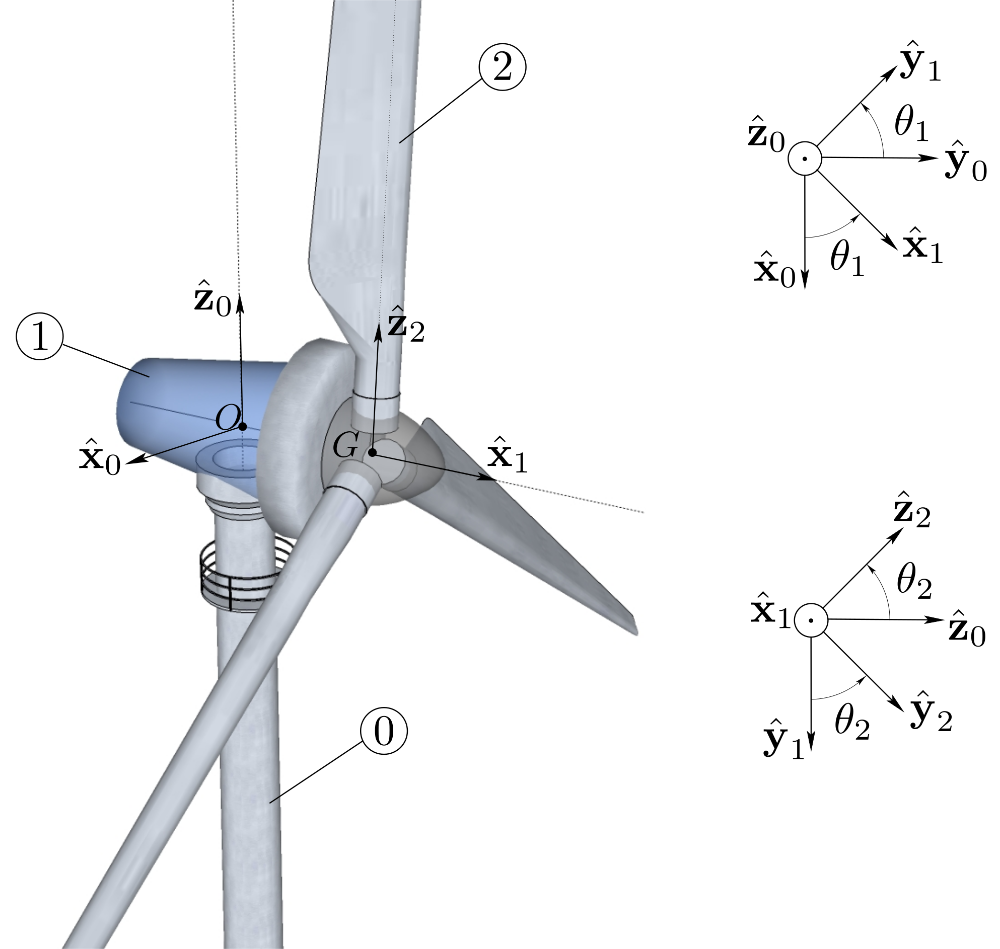
Figure 9.9.8 shows a model of a three-bladed wind turbine comprised of three interconnected bodies:
  1. the tower 0 is fixed relative to a referential \((O, \bx_0 , \by_0 , \bz_0)\) where \(\bz_0\) is a unit vector directed upward.
  2. the nacelle 1\((O, \bx_1, \by_1, \bz_0)\) is connected to the tower by a pivot of axis \((O, \bz_0)\text{:}\) 1 can rotate about axis \((O, \bz_0)\) with angle \(\theta_1 = (\bx_0 , \bx_1) = (\by_0 , \by_1)\text{.}\) The inertia operator of body 1 about \(O\) takes the following form
    \begin{equation*} [\cI_{O, 1}]_{b_1} = \begin{bmatrix} A_1 \amp F_1 \amp E_1 \\ F_1 \amp B_1 \amp D_1 \\ E_1 \amp D_1 \amp C_1 \end{bmatrix} _{b_1} \end{equation*}
    on basis \(b_1 (\bx_1, \by_1, \bz_0)\text{.}\)
  3. the rotor (which includes the blades) 2\((G, \bx_1 , \by_2, \bz_2)\) of mass \(m_2\) and mass center \(G\) is connected to the nacelle 1 by a pivot of axis \((O, \bx_1)\text{.}\) We denote by \(a\) the constant such that \(\br_{OG} = a \bx_1\text{.}\) The inertia operator of body 2 about \(G\) takes the following form
    \begin{equation*} [\cI_{G, 2}]_{b_2} = \begin{bmatrix} A_2 \amp 0 \amp 0 \\ 0 \amp B_2 \amp 0 \\ 0 \amp 0 \amp C_2 \end{bmatrix}_{b_2} \end{equation*}
    on basis \(b_2 (\bx_1, \by_2, \bz_2)\text{.}\)
Figure 9.9.8.
  1. Find angular momentum \(\bH_{O,1/0}\) of body 1 about \(O\) and angular momentum \(\bH_{G, 2/0}\) of body 2 about point \(G\text{.}\)
  2. Find component \(\bz_0 \cdot\bD_{O, \Sigma /0}\) of the dynamic moment of system \(\Sigma =\{1,2\}\) about \(O\text{.}\)
  3. Find component \(\bx_1 \cdot\bD_{G, 2 /0}\) of the dynamic moment of body 2 about \(G\text{.}\)
  4. Find the kinetic energy of system \(\Sigma\text{.}\)
Solution.
  1. Since \(O\) is a fixed point of body 1 (\(\vel_{O\in 1/0}=\bze\)), the angular momentum \(\bH_{O,1/0}\) is found from the knowledge of inertia operator \(\cI_{O,1}\) about \(O\) and angular velocity \(\bom_{1/0}=\dte_1 \bz_0\text{:}\)
    \begin{align*} \bH_{O,1/0}\amp = \cI_{O,1}(\bom_{1/0})= \begin{bmatrix} A_1 \amp F_1 \amp E_1 \\ F_1 \amp B_1 \amp D_1 \\ E_1 \amp D_1 \amp C_1 \end{bmatrix}_{b_1} \begin{bmatrix} 0 \\ 0 \\ \dte_1 \end{bmatrix}_{b_1}\\ \amp =\dte_1 (E_1\bx_1 + D_1 \by_1 + C_1 \bz_0) \end{align*}
    Similarly for body 2 of angular velocity \(\bom_{2/0}= \dte_1 \bz_0+ \dte_2 \bx_1\) and mass center \(G\text{,}\) we have
    \begin{align*} \bH_{G,2/0} \amp = \cI_{G,2}(\bom_{2/0})= \begin{bmatrix} A_2 \amp 0 \amp 0 \\ 0 \amp B_2 \amp 0 \\ 0 \amp 0 \amp C_2 \end{bmatrix}_{b_2} \begin{bmatrix} \dte_2 \\ \dte_1 \sin\te_2\\ \dte_1 \cos\te_2 \end{bmatrix}_{b_2}\\\\ \amp = A_2 \dte_2 \bx_1 + B_2 \dte_1 \sin\te_2\by_2 + C_2 \dte_1 \cos\te_2\bz_2 \end{align*}
  2. We find component \(\bz_0 \cdot\bD_{O, \Sigma /0}\) without finding \(\bD_{O, \Sigma /0}\) as follows:
    \begin{align*} \bz_0 \cdot\bD_{O, \Sigma /0} \amp = \bz_0 \cdot \frac{d}{dt} (\bH_{O, 1 /0}+ \bH_{O, 2/0} )\\ \amp = \frac{d}{dt} (\bz_0 \cdot\bH_{O, 1 /0}+ \bz_0 \cdot\bH_{O, 2/0} ) \end{align*}
    with
    \begin{align*} \bz_0 \cdot\bH_{O, 1 /0} \amp = \bz_0 \cdot \dte_1 (E_1\bx_1 + D_1 \by_1 + C_1 \bz_0)\\ \amp = C_1 \dte_1 \end{align*}
    and
    \begin{align*} \bz_0 \cdot\bH_{O, 2/0} \amp = \bz_0 \cdot(\bH_{G, 2/0} + \br_{OG}\times m_2 \vel_{G/0})\\ \amp = \bz_0 \cdot \dte_1(B_2 \sin\te_2\by_2 + C_2 \cos\te_2\bz_2) + \bz_0 \cdot (a\bx_1 \times m_2 a \dte_1 \by_1)\\ \amp = (B_2\sin^2\te_2 + C_2 \cos^2\te_2 + m_2 a^2) \dte_1 \end{align*}
    This gives the final result:
    \begin{equation*} \bz_0 \cdot\bD_{O, \Sigma /0} = \frac{d}{dt} \left( (C_1 + B_2\sin^2\te_2 + C_2 \cos^2\te_2 + m_2 a^2) \dte_1 \right) \end{equation*}
  3. We find the component \(\bx_1 \cdot\bD_{G, 2 /0}\) by using the following steps
    \begin{align*} \bx_1 \cdot\bD_{G, 2 /0} \amp = \bx_1 \cdot \frac{d}{dt} \bH_{G, 2 /0}\\ \amp = \frac{d}{dt} (\bx_1\cdot \bH_{G, 2 /0}) - \frac{d\bx_1}{dt} \cdot \bH_{G, 2 /0} \end{align*}
    with
    \begin{align*} \bx_1\cdot \bH_{G, 2 /0}\amp = \bx_1\cdot (A_2\dte_2 \bx_1 + B_2 \dte_1 \sin\te_2\by_2 + C_2 \dte_1 \cos\te_2\bz_2)\\ \amp = A_2 \dte_2 \end{align*}
    and
    \begin{align*} \frac{d\bx_1}{dt} \cdot \bH_{G, 2 /0} \amp = \dte_1 \by_1 \cdot (A_2\dte_2 \bx_1 + B_2 \dte_1 \sin\te_2\by_2 + C_2 \dte_1 \cos\te_2\bz_2)\\ \amp = (B_2 -C_2) \dte_1 \cos\te_2\sin\te_2 \end{align*}
    This gives the final result:
    \begin{equation*} \bx_1 \cdot\bD_{G, 2 /0}=A_2 \ddte_2 - (B_2 -C_2) \frac{d}{dt} (\dte_1 \cos\te_2\sin\te_2 ) \end{equation*}
  4. We find the kinetic energy of system \(\Sigma\) as follows
    \begin{align*} \kin_{\Si/0}\amp = \kin_{1/0}+ \kin_{2/0}\\ \amp = \half \bom_{1/0}\cdot \cI_{O,1}(\bom_{1/0}) + \half m_2 \vel_{G/0}^2 + \half \bom_{2/0}\cdot \cI_{G,2}(\bom_{2/0})\\ \amp = \half C_1\dte_1^2 + \half m_2 (a\dte_1 \by_1)^2 + \half \bom_{2/0}\cdot(A_2 \dte_2 \bx_1 + B_2 \dte_1 \sin\te_2\by_2 + C_2 \dte_1 \cos\te_2\bz_2)\\ \amp = \half C_1 \dte_1^2 + \half m_2 a^2\dte_1^2 +\half (A_2 \dte_2^2 + B_2 \dte_1^2 \sin^2\te_2 + C_2 \dte_1^2 \cos^2\te_2)\\ \amp = \half ( C_1 + m_2 a^2 + B_2 \sin^2\te_2 + C_2 \cos^2\te_2) \dte_1^2 + \half A_2 \dte_2^2 \end{align*}