Section 1.7 Finite Displacement of a Rigid Body

We propose in this section to study the finite displacements of rigid bodies, that is, mappings which take a configuration of rigid body \(\cB\) into new configurations in referential \(\cE\text{.}\) We start with a general definition of displacements.

Definition 1.7.1. Displacements.

Displacements are mappings of \(\cE\) which conserve distance and orientation.
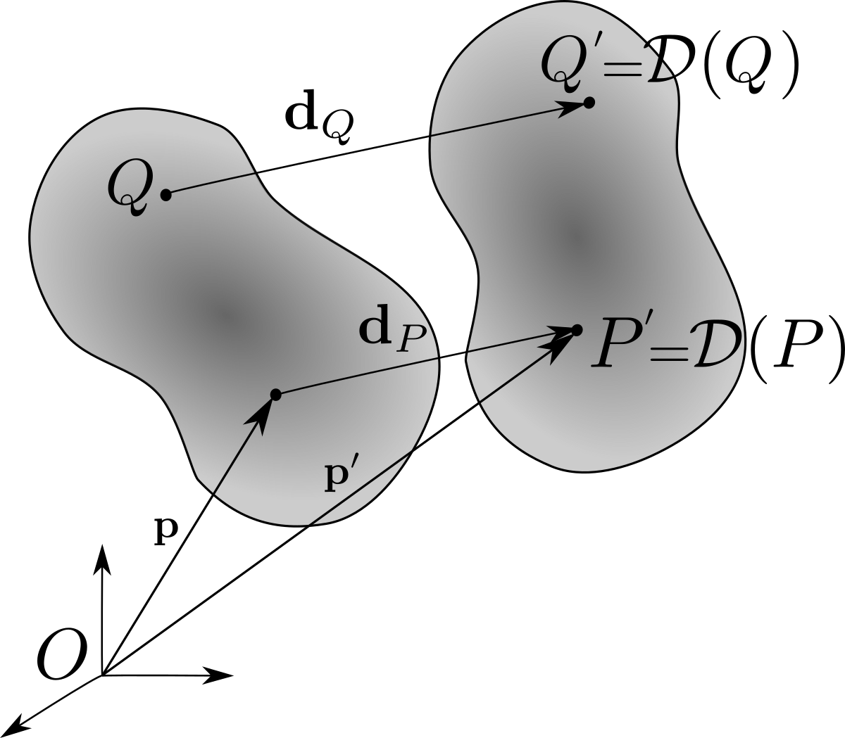
See Figure 1.7.5. Each point \(P\) of \(\cB\) is mapped by displacement \(\cD\) into a point \(P'\) with the following requirements:
  1. distances between points of \(\cB\) are conserved by \(\cD\text{:}\)
    \begin{equation*} |\bp- \bq| = |\bp'- \bq'| \end{equation*}
    denoting \(\bp = \br_{OP}\text{,}\) \(\bq = \br_{OQ}\text{,}\) \(\bp' = \br_{OP'}\text{,}\) and \(\bq' = \br_{OQ'}\text{.}\)
  2. oriented angles are conserved by \(\cD\text{.}\)
    \begin{equation*} (\bq-\bp, \br-\bp) = (\bq'-\bp', \br'-\bp') \end{equation*}
    for any three points \(P\text{,}\) \(Q\) and \(R\) attached to \(\cB\text{.}\)

Remark 1.7.2.

The set of displacements constitutes a group. It is a subgroup of the group of isometries of \(\cE\) (mappings in \(\cE\) which conserve distance).

Remark 1.7.3.

The set of all possible displacements is comprised of translations, rotations and their compositions.

Remark 1.7.4.

It will be useful to define the field of displacements \(P \in \cB \mapsto \bod_P = \bp'-\bp = \br_{PP'}\text{.}\)
Figure 1.7.5. Displacement

Subsection 1.7.1 Translation

Definition 1.7.6. Translation.

The translation \(\cT_\bl\) of vector \(\bl\) is the transformation defined by
\begin{equation} \cT_\bl: \; P\in \cB \mapsto P' =\cT_\bl(P) \quad \text{such that}\quad \bp' = \bp + {\bl}\tag{1.7.1} \end{equation}
Hence the field of displacements is invariant: \(\bod_P = \bl\) for all points of \(\cB\text{.}\) The transformation can be written in Cartesian coordinates on a basis \((\be_1,\be_2,\be_3)\) in the following form
\begin{gather*} x_1'=x_1+ l_1\\ x_2'=x_2+ l_2 \\ x_3'= x_3+ l_3 \end{gather*}
or in array form
\begin{equation*} \begin{bmatrix} x_1' \\ x_2'\\ x_3'\\ 1 \end{bmatrix} = [ \cT_\bl ] \begin{bmatrix} x_1 \\ x_2\\x_3\\ 1 \end{bmatrix} ,\qquad [ \cT_\bl ] = \begin{bmatrix} 1 \amp 0 \amp 0 \amp l_1 \\ 0 \amp 1 \amp 0 \amp l_2 \\ 0 \amp 0 \amp 1 \amp l_3 \\ 0 \amp 0 \amp 0 \amp 1 \end{bmatrix} \end{equation*}
The composition of two translations \(\cT_{l_1}\) and \(\cT_{l_2}\) is given by
\begin{equation*} \cT_{\bl_1}\circ \cT_{\bl_2}= \cT_{\bl_1+\bl_2} \end{equation*}
The translation of infinitesimal vector \(d\bl\) is represented by the matrix
\begin{equation*} [ \cT_{d\bl} ] = \begin{bmatrix} 1 \amp 0 \amp 0 \amp dl_1 \\ 0 \amp 1 \amp 0 \amp dl_2 \\ 0 \amp 0 \amp 1 \amp dl_3 \\ 0 \amp 0 \amp 0 \amp 1 \end{bmatrix} =[\cI] + dl_1 [ \cT_1 ] + dl_2 [ \cT_2 ] + dl_3 [ \cT_3 ] \end{equation*}
with
\begin{equation*} [\cI] = \begin{bmatrix} 1 \amp 0 \amp 0 \amp 0 \\ 0 \amp 1 \amp 0 \amp 0 \\ 0 \amp 0 \amp 1 \amp 0 \\ 0 \amp 0 \amp 0 \amp 0 \end{bmatrix} \quad [ \cT_1 ] = \begin{bmatrix} 0 \amp 0 \amp 0 \amp 1 \\ 0 \amp 0 \amp 0 \amp 0 \\ 0 \amp 0 \amp 0 \amp 0 \\ 0 \amp 0 \amp 0 \amp 0 \end{bmatrix} \quad [ \cT_2 ] = \begin{bmatrix} 0 \amp 0 \amp 0 \amp 0 \\ 0 \amp 0 \amp 0 \amp 1 \\ 0 \amp 0 \amp 0 \amp 0 \\ 0 \amp 0 \amp 0 \amp 0 \end{bmatrix} \quad [ \cT_3 ] = \begin{bmatrix} 0 \amp 0 \amp 0 \amp 0 \\ 0 \amp 0 \amp 0 \amp 0 \\ 0 \amp 0 \amp 0 \amp 1 \\ 0 \amp 0 \amp 0 \amp 0 \end{bmatrix} \end{equation*}
It is easy to verify that
\begin{equation*} [ \cT_i ] [ \cT_j ] = [0] \qquad (i,j=1,2,3) \end{equation*}
which leads to the property
\begin{equation*} e^{l_1 [\cT_1] +l_2 [\cT_2]+l_3 [\cT_3]} = [\cI]+ l_i [\cT_i])+ \frac{1}{2} l_i l_j [\cT_i] [\cT_j] + \ldots = [\cI]+l_1 [\cT_1] +l_2 [\cT_2]+l_3 [\cT_3] \end{equation*}
This shows that matrix \([\cT_\bl ]\) can be expressed in terms of the components \([\cT_i]\) according to:
\begin{equation} [\cT_\bl ]= e^{l_1 [\cT_1] +l_2 [\cT_2]+l_3 [\cT_3]}\tag{1.7.2} \end{equation}

Subsection 1.7.2 Rotation

Definition 1.7.7. Rotation.

A rotation is a transformation which leaves a point \(O\) of \(\cB\) invariant and conserves the orientation of a basis of \(\cB\text{.}\) The rotation \(\cR_O\) about \(O\text{,}\) of angle \(\alpha\text{,}\) and direction \(\bu\) is characterized by
\begin{equation*} \cR_O : P \in \cB \mapsto P' = \cR_O (P) \quad \text{such that}\quad \bp' = \cR_{\al,\bu} (\bp) \end{equation*}
The displacement field can be expressed as \(\bod_P = \sin\al \bu\times \bp + (1-\cos\al)\bu\times(\bu\times \bp)\) according to Rodrigues formula. All points of the axis of rotation \(\Delta (O,\bu)\) are invariant by the rotation: \(\bod_P =0\) for all \(P \in \Delta\text{.}\) The transformation can be written in Cartesian coordinates on a basis \((\be_1,\be_2,\be_3)\) in various forms
\begin{equation*} \begin{bmatrix} x_1' \\ x_2'\\ x_3' \end{bmatrix} = [ \cR_O ] \begin{bmatrix} x_1 \\ x_2\\x_3 \end{bmatrix} ,\qquad [ \cR_O ] = \begin{bmatrix} r_{11} \amp r_{12}\amp r_{13} \\ r_{21} \amp r_{22} \amp r_{23} \\ r_{31} \amp r_{32} \amp r_{33}\\ \end{bmatrix} \end{equation*}
where the coefficients \(r_{ij}\) can be expressed in terms of the direction cosines \(c_{ij}= \be_i \cdot \bhb_j\) (Section 1.3), in terms of Euler angles (Section 1.4), or in terms of Euler parameters \((\al, \bu)\) (Section 1.5).
The infinitesimal rotation \(\cR_{d\al,\bu}\) of angle \(d\al\) about \(\bu\) maps point \(P\) to \(P'\) according to
\begin{equation*} \cR_{d\al,\bu} (\bp) = \bp + d\al \bu \times\bp \end{equation*}
and the corresponding matrix on basis \(b (\be_1,\be_2,\be_3)\) is given by
\begin{equation*} [\cR_{d\al,\bu}]_b = [\cI] + d\al \begin{bmatrix} 0 \amp -u_3 \amp u_2 \\ u_3 \amp 0 \amp u_1 \\ -u_2 \amp -u_1 \amp 0\\ \end{bmatrix} = [\cI] + d\al ( u_1 [\cR_1]_b +u_2 [\cR_2]_b + u_3 [\cR_3]_b ) \end{equation*}
where \((u_1,u_2,u_3)\) are the components of \(\bu\) on basis \(b\) and with
\begin{equation*} [\cR_1]_b = \begin{bmatrix} 0 \amp 0 \amp 0 \\ 0 \amp 0 \amp 1 \\ 0 \amp -1 \amp 0\\ \end{bmatrix}, \quad [\cR_2]_b =\begin{bmatrix} 0 \amp 0 \amp 1 \\ 0 \amp 0 \amp 0 \\ -1 \amp 0 \amp 0\\ \end{bmatrix} , \quad [\cR_3]_b = \begin{bmatrix} 0 \amp -1 \amp 0 \\ 1 \amp 0 \amp 0 \\ 0 \amp 0 \amp 0\\ \end{bmatrix} \end{equation*}

Subsection 1.7.3 Screw Displacement

The most general displacement can be considered to be a composition of a translation and a rotation. Using Rodrigues formula, it is possible to obtain a coordinate-free expressions of displacements.

Proof.

Consider a particular point \(A\) of \(\cB\) which is mapped into \(A'\text{.}\) Then consider the mapping \(\bp - \ba \mapsto \bp'-\ba'\text{.}\) This map leaves \(A\) invariant. Hence the vector \(\bp' -\ba'\) can be obtained from \(\bp -\ba\) by a (vectorial) rotation \(\cR\) such that:
\begin{equation*} \bp' -\ba' = \cR (\bp -\ba) \end{equation*}
which gives
\begin{equation*} \bp' = \ba'- \cR (\ba) + \cR (\bp) = \bl + \cR (\bp) \end{equation*}
It is easy to show that \(\cR\) is not a function of the choice of \(A\text{.}\) Using Rodrigues formula, there exist an angle \(\al\) and a unit vector \(\bu\) such that
\begin{equation} \cR (\bp) = \bp + \sin\alpha \bu\times\bp + (1- \cos\alpha) \bu\times(\bu\times\bp)\tag{1.7.4} \end{equation}
We then need to show that the operator \(e^{\al \cU}\) is equivalent to Rodrigues formula. This operator can be defined as the expansion
\begin{equation*} e^{\al \cU} = \cI + \al \cU + \frac{\al^2}{2!} \cU^2 + \frac{\al^3}{3!} \cU^3 + \cdots \end{equation*}
It is easy to show that operator \(\cU\) satisfies:
\begin{equation*} \cU^{2k} = (-1)^{k-1} \cU^2, \qquad \cU^{2k-1} = (-1)^{k-1} \cU \qquad (k\geq 1) \end{equation*}
We can then express operator \(e^{\al \cU}\) as
\begin{align*} e^{\al \cU} \amp = \cI + (\al - \frac{\al^3}{3!} + \frac{\al^5}{5!} + \cdots ) \cU + (\frac{\al^2}{2!} - \frac{\al^4}{4!} + \cdots )\cU^2\\ \amp = \cI + \sin\al \, \cU + (1-\cos\al) \cU^2 \end{align*}

Remark 1.7.9.

In general, a displacement which is not a rotation \((\bl\neq \bze)\) does not have any fixed points, that is, points undergoing no displacement. Such points would satisfy \((\cR -\cI) (\bp) = \bl\text{.}\) However the operator \(\cR -\cI\) is singular since \(\la=1\) is an eigenvalue of \(\cR\text{.}\) There are no such points.
An important characterization of displacements can be established by seeking the set of points which have minimal displacement, that is, which minimize
\begin{equation*} |\bp'-\bp|^2 = |(\cR -\cI)\bp + \bl|^2 \end{equation*}
The minimization yields the solution \((\cR-\cI) (\bp'-\bp) = 0\text{.}\) Since the eigenvectors of \(\cR\) corresponding to eigenvalue \(\la=1\) are the vectors collinear to \(\bu\text{,}\) we find that the points with minimum-norm displacement satisfy
\begin{equation*} \bp'-\bp = \mu \bu, \qquad \mu \in \mathbb{R} \end{equation*}
Hence, the minimum-norm displacement lies along the axis of rotation \(\cR\text{.}\) Conversely, the points whose displacements are parallel to the rotation axis lie on an axis parallel to \(\bu\text{.}\) Indeed, let point \(Q\) satisfy \(\bq = \bp + \nu \bu\) where \(\nu\) is an arbitrary scalar and where \(\bp\) satisfies \(\bp' -\bp = \mu \bu\text{.}\) Then \(\bq'-\bq = \cR (\bq) + \bl - \bq = \cR(\bp) + \bl -\bp = \bp'-\bp = \mu \bu\text{.}\) Hence all points of this axis have the same displacement. In conclusion,
It is then possible to derive a coordinate-free expression of the displacement, independent of the choice of origin \(O\text{.}\) First we need to find a particular point of the screw axis: such points are solution of the equation
\begin{equation} \bod_P= \bp' -\bp = \mu \bu = \sin\al \bu \times \bp + (1-\cos\al) \bu\times (\bu \times \bp) + \bl\tag{1.7.5} \end{equation}
We eliminate the unknown \(\mu \bu\) by taking the cross-product of this equation with \(\bu\) to obtain
\begin{equation} \bze = \sin\al \bu \times (\bu \times \bp) + (1-\cos\al) \bu \times \big(\bu\times (\bu \times \bp) \big) +\bu\times\bl \tag{1.7.6} \end{equation}
Let \(P^*\) the point of the screw axis satisfying \(\bp^* \cdot \bu\text{.}\) \(P^*\) is the foot of the perpendicular drawn from origin \(O\) to the screw axis. Then equation (1.7.6) becomes, using \(\bu \times (\bu \times \bp^*) = -\bp^*\text{:}\)
\begin{equation*} \sin\al \bp^* + (1-\cos\al) \bu\times \bp^* -\bu\times\bl = \bze \end{equation*}
and after taking the cross-product with \(\bu\)
\begin{equation*} \sin\al \bu\times \bp^* - (1-\cos\al) \bp^* -\bu\times(\bu\times\bl) = \bze \end{equation*}
Now we can solve for \(\bp^*\text{:}\)
\begin{equation} \bp^* = \frac{1}{2} \cot\frac{\al}{2} \, \bu\times\bl - \frac{1}{2}\bu\times(\bu\times\bl)\tag{1.7.7} \end{equation}
The screw axis \(\Delta\) is then the set of points defined by
\begin{equation*} \Delta = \{Q \,|\, \bq = \bp^* + \nu \bu,\quad \nu \in \mathbb{R} \} \end{equation*}
The general expression of the displacement is then
\begin{equation*} \bp' =\bl + e^{\al \bU} (\bp) = \bl + e^{\al \bU} (\bp^*) + e^{\al \bU}(\bq-\bp^*) + e^{\al \bU}(\bp-\bq) \end{equation*}
where \(Q\) is an arbitrary point of \(\Delta\text{.}\) We then find
\begin{equation*} e^{\al \bU}(\bq-\bp^*) = (\bq-\bp^*), \qquad e^{\al \bU} (\bp^*) = \bu\times (\bu \times \bl) + \bp^* \end{equation*}
Finally we obtain
\begin{equation} \bp' - \bq = \la \bu + e^{\al \bU}(\bp-\bq)\tag{1.7.8} \end{equation}
with \(\la = \bu\cdot \bl\text{.}\) We conclude that the most general displacement of a rigid body is entirely defined by the following geometric quantities:
  • the screw displacement \(\la\text{.}\)
  • a point \(P^*\) of the screw axis \(\Delta\) whose position is defined by (1.7.7),
  • the direction \(\bu\) of \(\Delta\) along and about which the body translates and rotates,
  • the angle of rotation \(\al\text{.}\)
Figure 1.7.11. Screw displacement
These results can be summarized by the following theorem (see Figure 1.7.11).

Remark 1.7.13.

The displacement of all points of \(\Delta\) is the quantity \(\la = \bu\cdot \bl = h\alpha /2\pi\text{.}\)

Remark 1.7.14.

The position of the screw axis changes relative to both \(\cB\) and \(\cE\) from one configuration to the next.

Remark 1.7.15.

Displacements can be classified according to the set of their fixed points, that is, of points satisfying \(\cD (P) = P\text{:}\)
  1. if all points are fixed points, \(\cD\) is the identity,
  2. if there are no fixed points, \(\cD\) is either a translation or a screw displacement,
  3. if the set of fixed points is a line, then \(\cD\) is a rotation.

Example 1.7.16.

Consider the mapping \(P (x_1,x_2,x_3) \in \cB \mapsto P'(x_1',x_2',x_3')\) defined by the following equations
\begin{equation*} \begin{cases} x_1' \amp = \frac{1}{4}(x_1+ 3 x_2 -\sqrt{6} x_3 ) +1 \\ x_2' \amp = \frac{1}{4}(3x_1+ x_2 +\sqrt{6} x_3) +1 \\ x_3' \amp = \frac{1}{4}(\sqrt{6} x_1-\sqrt{6} x_2 -2x_3)-1 \end{cases} \end{equation*}
Show that this mapping corresponds to a screw displacement. Find the characteristics of this displacement (screw axis, angle and pitch).
Solution.
The mapping can be written in the following form:
\begin{equation*} \bp'= \bl + \cR (\bp), \qquad [\bl]_E = \begin{bmatrix} 1\\ 1\\ -1\\ \end{bmatrix} \qquad [\cR]_E = \frac{1}{4} \begin{bmatrix} 1 \amp 3 \amp -\sqrt{6} \\ 3 \amp 1 \amp \sqrt{6} \\ \sqrt{6} \amp -\sqrt{6} \amp -2\\ \end{bmatrix} \end{equation*}
We must check that matrix \([\cR]_E\) corresponds to a rotation: if we denote the column vectors \((\bc_1,\bc_2,\bc_3)\) we can verify that \(\bc_i \cdot \bc_j =\delta_{ij}\) and that \(\bc_3 = \bc_1 \times \bc_2\text{.}\) Since \(\bl\neq 0\text{.}\) this mapping is necessarily a displacement.
We can find the direction of the corresponding screw axis by determining the set of invariant vectors by \(\cR\text{.}\) that is, satisfying \(\cR(\bV) = \bV\text{:}\)
\begin{equation*} \begin{cases} \amp x_1+ 3 x_2 -\sqrt{6} x_3 =4x_1 \\ \amp 3x_1+ x_2 +\sqrt{6} x_3 =4x_2 \\ \amp \sqrt{6} x_1-\sqrt{6} x_2 -2x_3 =4x_3 \end{cases} \end{equation*}
These equations are equivalent to
\begin{equation*} x_1 = x_2, \qquad x_3=0 \end{equation*}
We may choose \(\bu = (\be_1 + \be_2)/\sqrt{2}\) as the direction of the screw axis. The corresponding angle \(\al\) is found by finding \(\cos\al\) and \(\sin\al\text{:}\)
\begin{equation*} 2\cos\al +1 = \text{tr}(\cR) = 0, \qquad \sin\al = (\bv, \cR(\bv), \bu) =- \frac{\sqrt{3}}{2} \end{equation*}
by choosing \(\bv = \be_3\) (normal to \(\bu\text{.}\) This gives \(\al = 4\pi/3\text{.}\) Finally, we find \(\cR = \cR_{4\pi/3,\bu}\text{.}\)
The screw displacement is given by \(\la = \bl \cdot \bu = \sqrt{2}\text{.}\) since \(\la\neq 0\text{.}\) the displacement is a screw displacement. To find the screw axis, we can find point \(P^*\) by applying formula (1.7.7), or we can find the set of points \(P\) whose displacement is \(\sqrt{2} \bu\text{,}\) that is, such that \(\bp'-\bp = \sqrt{2}\bu\text{.}\)
\begin{equation*} \begin{cases} \amp -3 x_1+ 3 x_2 -\sqrt{6} x_3 =0 \\ \amp 3x_1-3 x_2 +\sqrt{6} x_3 = 0 \\ \amp \sqrt{6} x_1-\sqrt{6} x_2 -6x_3 =-1 \end{cases} \end{equation*}
This gives the axis \(\Delta (A, \bu)\) with \(A(1/\sqrt{6},0,-1/2)\text{.}\) It is easy to verify that the point \(P^*\) given by
\begin{equation*} \br_{OP^*}= \frac{1}{2} \cot\frac{\al}{2} \, \bu\times\bl - \frac{1}{2}\bu\times(\bu\times\bl) = \frac{\be_1}{2\sqrt{6}} - \frac{\be_2}{2\sqrt{6}} - \frac{\be_3}{2} \end{equation*}
lies on axis \(\Delta\text{.}\)

Subsection 1.7.4 Displacements Under Small Angle Rotations

Consider a rigid body \(\cB (B, \bhb_1,\bhb_2,\bhb_3)\) in a referential \(\cE (O,\be_1,\be_2,\be_3)\text{.}\) Assume that body \(\cB\) undergoes a displacement \(\cD\) which takes every point \(P\) to a new position \(P'\text{.}\) We can then write the following equation between the positions of any two points \(P\) and \(Q\) of \(\cB\text{:}\)
\begin{equation*} \bq' - \bq = (\cR -\cI) (\bq -\bp) + \bp'-\bp \end{equation*}
The displacements of \(P\) and \(Q\) are then related by the equation
\begin{equation*} \bod_Q = \bod_P + (\cR -\cI) (\bq-\bp) \end{equation*}
The operator \(\cR= \cR_{EB}\) is the rotation which maps basis \((\be_1,\be_2,\be_3)\) of \(\cE\) to basis \((\bhb_1,\bhb_2,\bhb_3)\) of \(\cB\text{.}\) Assume that the orientation of \(\cB\) is parametrized by Bryant angles according to the transforms
\begin{equation*} (\be_1 , \be_2 , \be_3 ) \xrightarrow{\cR_{\psi , \be_3}} (\bu_1 , \bu_2 ,\bu_3= \be_3 ) \xrightarrow{ \cR_{\theta , \bu_2}} (\bv_1, \bv_2=\bu_2 , \bv_3 ) \xrightarrow{\cR_{\phi , \bv_1}} (\bhb_1= \bv_1 , \bhb_2 , \bhb_3 ) \end{equation*}
According to Section 1.4, the corresponding rotation matrix is found to be
\begin{equation*} [\cR_{EB}]_E = [\cC_{EB}] = \begin{bmatrix} c_\psi c_\te \amp c_\psi s_\te s_\phi -s_\psi c_\phi \amp c_\psi s_\te c_\phi+ s_\psi s_\phi \\ s_\psi c_\te \amp s_\psi s_\te s_\phi +c_\psi c_\phi \amp s_\psi s_\te c_\phi-c_\psi s_\phi \\ -s_\te \amp c_\te s_\phi \amp c_\te c_\phi \end{bmatrix} \end{equation*}
Let us assume a small angle rotation, that is, small values of the angles \((\psi,\te,\phi)\text{.}\) By keeping only the terms of order 1 in \((\psi,\te,\phi)\) we find that the rotation matrix takes the following form
\begin{equation*} [\cR_{EB}]_E = [\cC_{EB}] = \begin{bmatrix} 1 \amp -\psi \amp \te \\ \psi \amp 1 \amp -\phi \\ -\te \amp \phi \amp 1 \end{bmatrix} \end{equation*}
Hence, matrix \([\cR_{EB}- \cI]_E\) takes the form:
\begin{equation*} [\cR_{EB}- \cI]_E = \begin{bmatrix} 0 \amp -\psi \amp \te \\ \psi \amp 0 \amp -\phi \\ -\te \amp \phi \amp 0 \end{bmatrix} \end{equation*}
We conclude that the operator \(\cR_{EB}- \cI\) is skew-symmetric, and that it can be expressed as
\begin{equation} (\cR_{EB}- \cI) (\bq-\bp) = \boldsymbol{\Omega} \times \br_{PQ}\tag{1.7.10} \end{equation}
with \(\boldsymbol{\Omega}= \phi \be_1 + \te \be_2 + \psi \be_3\text{.}\) This leads to the following theorem.

Remark 1.7.18.

It can be seen that the rotation vector is an invariant of the body (for small angle rotations): it is not a function of position or of the chosen coordinate system.

Remark 1.7.19.

Vector fields satisfying the property \(\vel_Q = \vel_P + \bV \times \br_{PQ}\) play a central role in rigid-body mechanics. They will be studied in Chapter 4.