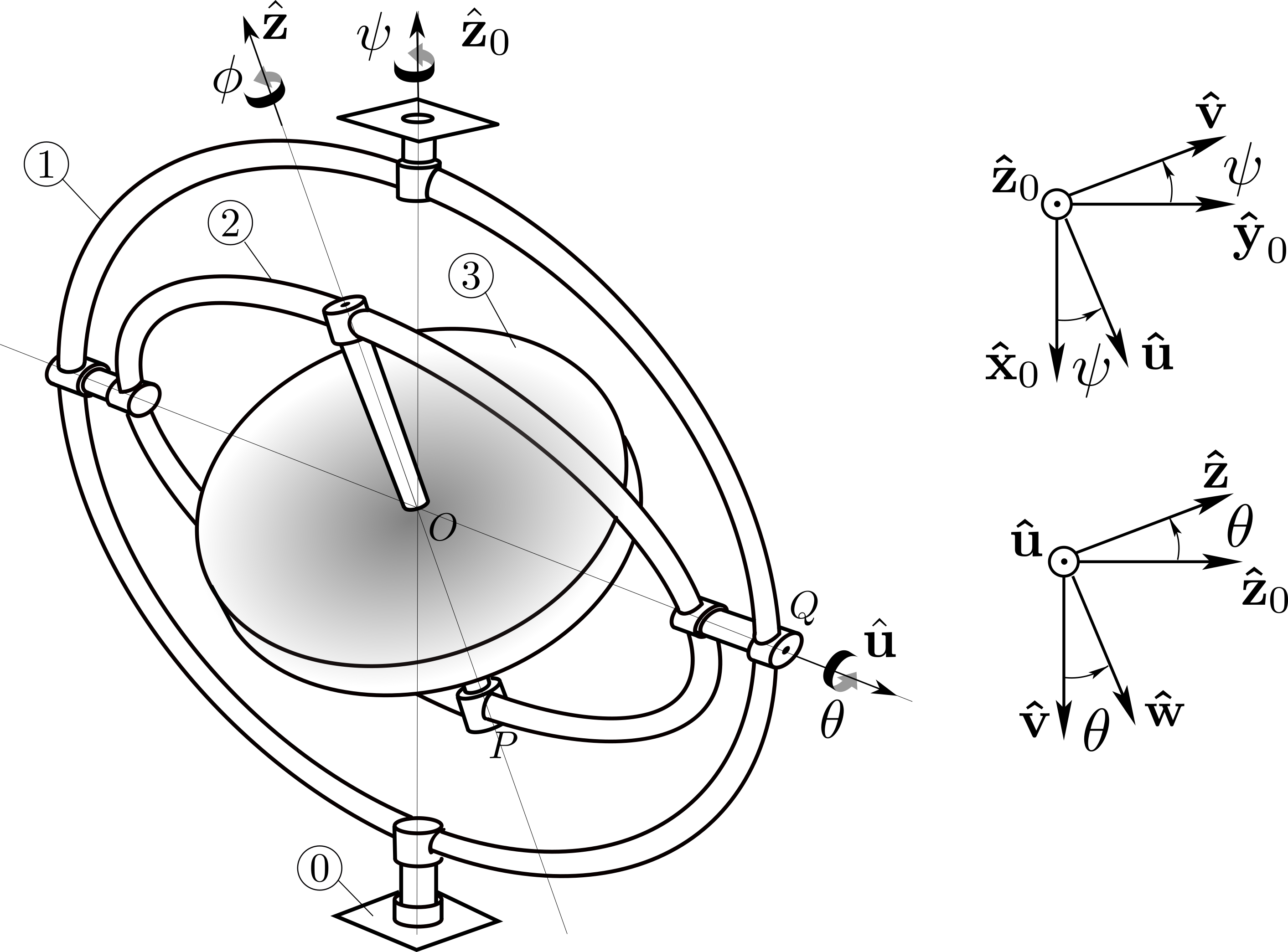
a. Force \(F_P \bw\) creates an external moment \(\bM_O = -r \bz\times F_P\bw = r F_P \bu\) applied to body 3. Application of the dynamic moment equation \(d\bH_O /dt = \bM_{O, \bar{3}\to 3}\) gives
\begin{equation*}
C \dphi \frac{d\bz}{dt} = rF_P \bu + \bM^c_{O, 2 \to 3}
\end{equation*}
To evaluate \(d \bz /dt\) we use the angular velocity \(\bom_{2 /0} = \dpsi\bz_0 + \dte \bu\text{:}\)
\begin{equation*}
\frac{d\bz}{dt} = (\dpsi\bz_0 + \dte \bu) \times \bz = \dpsi \sin\te \bu - \dte \bw
\end{equation*}
Hence we obtain
\begin{equation*}
C \dphi (\dpsi \sin\te \bu - \dte \bw) = rF_P \bu + \bM^c_{O, 2 \to 3} \quad {(1)}
\end{equation*}
Before resolving (1) on basis \((\bu, \bw, \bz)\) we need the components of \(\bM^c_{O, 2 \to 3} = L \bu + M \bw\) (the component on \(\bz\) is zero since the pivot between 2 and 3 is frictionless). They can be found by writing the ``equilibrium’’ of (massless) body 2:
\begin{equation*}
\bM^c_{O, 3 \to 2} + \bM^c_{O, 1 \to 2} = \bze
\end{equation*}
Since \(\bM^c_{O, 1 \to 2}\cdot \bu =0\text{,}\) this gives \(L=0\text{.}\) Then equilibrium of body 1 gives
\begin{equation*}
\bM^c_{O, 0 \to 1} + \bM^c_{O, 2 \to 1} = \bze
\end{equation*}
Again the condition \(\bM^c_{O, 0\to 1} \cdot \bz_0 = 0\) (the pivot between 0 and 1 is frictionless) necessarily implies \(M=0\text{.}\) Therefore, after taking into account \(L=M=0\text{,}\) equation (1) now leads to
\begin{equation*}
\dte =0, \qquad C \dphi \dpsi \sin\te = rF_P
\end{equation*}
This shows that angle \(\theta\) remains constant, and that the gyroscope slowly precesses at constant angular velocity
\begin{equation*}
\dpsi = \frac{rF_P}{C \dphi \sin\te_0}
\end{equation*}
about axis \((O,\bz_0)\text{.}\) One would expect that application of force \(F_P\) would lead to a rotation about axis \((O,\bu)\text{.}\) But in fact the gyroscope precesses at a right angle to the applied force.
b. Force \(F_Q \bv\) leads to a moment \(R \bu \times F_Q \bv = RF_Q \bz_0\) about \(O\) acting on body 1. Equilibrium of gimbal 1 translates into
\begin{equation*}
RF_Q \bz_0 + \bM^c_{O, 0 \to 1}+ \bM^c_{O, 2 \to 1} = \bze
\end{equation*}
Since \(\bz_0 \cdot \bM^c_{O, 0 \to 1} = 0\text{,}\) this leads to the equation
\begin{equation*}
RF_Q + (M_{12}\bw + N_{12} \bz)\cdot\bz_0 = 0
\quad{(2)}
\end{equation*}
where we have written \(\bM^c_{O, 2 \to 1} = M_{12}\bw + N_{12} \bz\) (the component on \(\bu\) is zero). On the other hand, equilibrium of body 2 implies that
\begin{equation*}
\bM^c_{O, 3 \to 2} + \bM^c_{O, 1 \to 2} = \bze \quad {(3)}
\end{equation*}
Since \(\bM_{O, 3 \to 2} \cdot \bz = 0\) this leads to \(N_{12} =0\text{.}\) Equation (2) then gives \(RF_Q = -M_{12} \sin\te\text{.}\) Finally we obtain from (3)
\begin{equation*}
\bM^c_{O, 2 \to 3} = - \bM^c_{O, 2 \to 1} = - M_{12} \bw =
\frac{RF_Q}{\sin\te} \bw
\end{equation*}
Now as in a), we apply the dynamic moment equation \(d\bH_O /dt = \bM_{0, \bar{3}\to 3}\) to obtain
\begin{equation*}
C \dphi (\dpsi \sin\te \bu - \dte \bw) = \bM^c_{O, 2 \to 3} = \frac{RF_Q}{\sin\te} \bw
\end{equation*}
leading to
\begin{equation*}
C \dphi \dpsi \sin\te = 0 , \qquad C \dphi \dte = -\frac{RF_Q}{\sin\te}
\end{equation*}
This shows that angular velocity \(\dpsi\) is zero: the moment \(RF_Q \bz_0\) exerted on gimbal 1 does not lead to the rotation of gimbal 1 about axis \((O,\bz_0)\text{.}\) Instead it produces the rotation of gimbal 2 about axis \((O, \bu)\) with angular velocity
\begin{equation*}
\dte = -\frac{RF_Q}{C \dphi \sin\te}
\end{equation*}
This equation can be integrated to give
\begin{equation*}
\cos\te = \cos\te_0 + \frac{RF_Q}{C \dphi} t
\end{equation*}
which shows that angle \(\theta\) decreases toward the value \(\theta =0\text{:}\) gimbal 2 eventually reaches the vertical position, its plane coinciding with that of gimbal 1. At this point, the axes \((O,\bz_0)\) and \((O,\bz)\) coincide, the gyroscopic effect ceases, and the rotation of gimbal 1 proceeds.

