Section 15.6 Applications
Example 1: The Precession of the Equinoxes. The precession of the equinoxes is a phenomenon that has been known since the Greek antiquity. It is due to the periodic precession of the Earth’s axis of rotation with a corresponding period of about 26,000 years. The precession can be predicted as the gyroscopic effect created by the gravitational forces of the Sun and the Moon on the Earth: due to the oblate spheroidal shape of the Earth, and to its axial tilt relative to its ecliptic plane, these forces create a non-zero moment about the mass center of the Earth acting perpendicularly to the axis of rotation. This moment thus leads to the axis’ precession which we propose to study here.
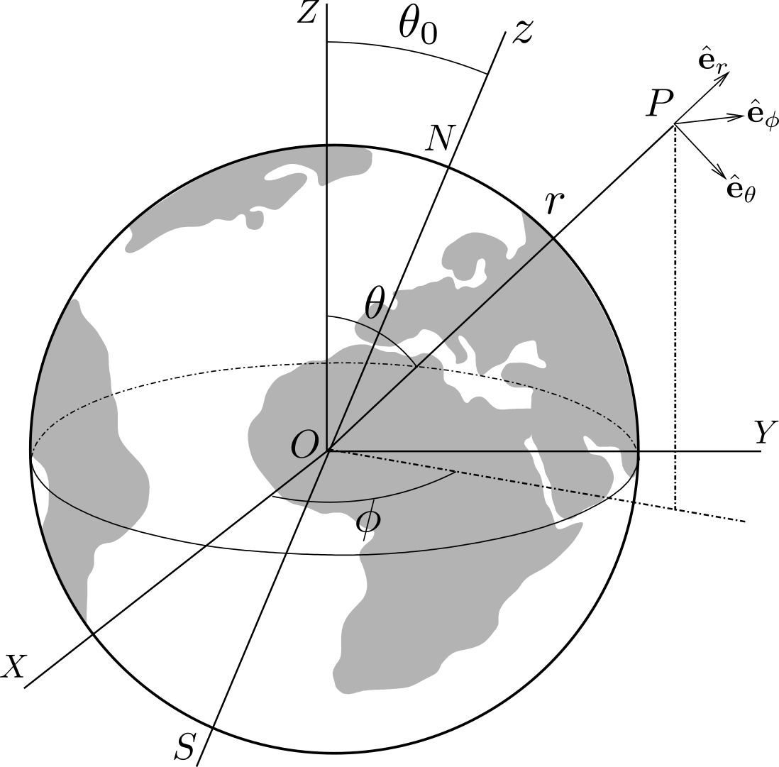
Figure 15.6.1 shows the Earth \(\cE\) of mass center \(O\text{,}\) mass \(m_E\text{,}\) radius \(R_E\) and angular velocity \(\Omega_E\) about axis of rotation \(Oz\text{.}\) The Cartesian axes \(OXYZ\) are chosen so that axis \(OZ\) is perpendicular to the Earth’s ecliptic plane \(OXY\text{,}\) with axis \(OX\) perpendicular to the plane \(OZz\text{.}\) Axis of rotation \(Oz\) is assumed inclined with a constant angle \(\theta_0\) relative to axis \(OZ\text{.}\) The Earth’s gravitational potential at a point \(P\) of spherical coordinates \((r, \phi, \theta)\) located at a distance \(r \gg R_E\) from \(O\) can be shown to be given by
\begin{equation*}
\pot = - \frac{Gm_E}{r} - (C-A) \frac{G}{2r^3} [ 1 -3(\sin\te\sin\phi\sin\te_0 +\cos\te\cos\te_0)^2 ]
\end{equation*}
where \(C\) is the axial moment of inertia, and \(A\) the equatorial moment of inertia of the Earth.

- Show that the Earth’s gravitational field at a point \(P\) located in the ecliptic plane (\(\theta = \pi /2\)) is given by\begin{equation*} \bG_P = (C-A) \frac{3G}{2r^4} [ \sin2\te_0 \sin\phi \,\be_\te -\sin^2\te_0 \sin2\phi \,\be_\phi] \end{equation*}Deduce that a celestial body of mass \(M_P\) located at \(P\) exerts on Earth an average moment about \(O\) given by\begin{equation*} \bM_O = (C-A) \frac{3GM_P}{4r^3} \sin2\te_0 \be_X \end{equation*}
- By including the contribution of the Sun (mass \(M_s\text{,}\) distance \(r_s\)) and the Moon (mass \(M_m\text{,}\) distance \(r_m\)) in the expression of \(\bM_O\text{,}\) show that the axis of rotation \(Oz\) precesses (relative to the Heliocentric referential) at the rate\begin{equation*} \bom = - \frac{C-A}{C} \frac{3G\cos\te_0}{2\Omega_E} \left( \frac{M_s}{r_s^3} + \frac{M_m}{r_m^3} \right) \be_Z \end{equation*}With \((C-A)/C = 1/308\text{,}\) \(\te_0 = 23^o 27'\text{,}\) \({M_m}/ {r_m^3} = 2.17 {M_s}/{r_s^3}\text{,}\) \(M_s/ r_s^3 = 4\pi^2 / G T^2\) (according Kepler’s 3rd law, with \(T\) the period of revolution of \(\cE\) around the Sun), find numerically (in time unit of years) the corresponding period of the precessional motion.
Solution 1.
a. The Earth’s gravitational field at a point \(P\) is found from the potential \(\pot\) according to \(\bG_P = -\grad \pot\text{,}\) which gives in spherical coordinates \((r,\te ,\phi)\text{:}\)
\begin{equation*}
\bG_P = - \frac{\partial \pot}{\partial r} \be_r -\frac{1}{r} \frac{\partial \pot}{\partial \te} \be_\te
- \frac{1}{r\sin\te} \frac{\partial \pot}{\partial \phi} \be_\phi
\end{equation*}
This gives the components
\begin{equation*}
G_\te = - 6(C-A) \frac{G}{2r^4}(\sin\te\sin\phi\sin\te_0 +\cos\te\cos\te_0)(\cos\te\sin\phi\sin\te_0-\sin\te\cos\te_0)
\end{equation*}
\begin{equation*}
G_\phi = - 6(C-A) \frac{G}{2r^4}(\sin\te\sin\phi\sin\te_0 +\cos\te\cos\te_0)\cos\phi\sin\te_0
\end{equation*}
In the ecliptic plane, \(\te=\pi/2\text{,}\) the \(G_\te\) and \(G_\phi\) components simplify to
\begin{equation*}
G_\te = 3(C-A) \frac{G}{2r^4}\sin\phi\sin 2\te_0, \qquad
G_\phi =- 3(C-A) \frac{G}{2r^4}\sin2\phi\sin^2\te_0
\end{equation*}
The moment \(\bM_O\) of the forces exerted on Earth by a celestial body of mass \(M_P\) located at \(P\) is the opposite of the moment \(\br_{OP} \times M_P \bG_P\) which Earth exerts on \(P\text{:}\) it is given by
\begin{align*}
\bM_O \amp = - r\be_r \times M_P (G_r \be_r + G_\te\be_\te + G_\phi \be_\phi) = -M_P r (G_\te \be_\phi - G_\phi\be_\te)\\
\amp = -M_P r (-G_\te \sin\phi \be_X + G_\te \cos\phi \be_Y + G_\phi \be_Z)\\
\amp = 3(C-A) \frac{GM_P}{2r^3} (\sin^2\phi\sin 2\te_0 \be_X - \sin\phi\cos\phi\sin 2\te_0 \be_Y +\sin2\phi\sin^2\te_0 \be_Z)
\end{align*}
When Earth rotates, the angle \(\phi\) exhibits rapid variations and the moment \(\bM_O\) can be averaged by taking into account \(\langle\sin^2\phi \rangle = 1/2\) and \(\langle\sin\phi\cos\phi \rangle = 0\text{:}\) this gives the average value
\begin{equation*}
\bM_O = 3(C-A) \frac{GM_P}{4r^3} \sin 2\te_0 \be_X \qquad{(1)}
\end{equation*}
b. In the geocentric referential, the Earth rotates at angular velocity \(\Om_E \be_z\text{.}\) The gyroscopic effect due to the gravitation perturbation is predicted as a balance of gravitational moment \(\bM_O\) and the gyroscopic couple \(\bGa_g = - C \Omega_E \frac{d\bz}{dt}\text{:}\)
\begin{equation*}
\frac{3}{4}G(C-A)( \frac{M_s}{r_s^3} +\frac{M_m}{r_m^3}) \sin 2\te_0 \be_X- C \Omega_E \frac{d\bz}{dt} = \bze
\end{equation*}
using the expression (1) of \(\bM_O\) for the contributions of the Sun and the Moon. This equation shows that \(\bM_O\) causes a slow precessional rotation about axis \(OZ\) at angular velocity \(\bom = \om \be_Z\) such that
\begin{equation*}
\frac{d\bz}{dt} = \om\be_Z \times \be_z = - \om \sin\te_0 \be_X
\end{equation*}
This gives \(\bom\text{:}\)
\begin{equation*}
\bom = -\left(\frac{C-A}{C}\right) \frac{3G\cos\te_0}{2\Omega_E} ( \frac{M_s}{r_s^3} +\frac{M_m}{r_m^3}) \be_Z
\end{equation*}
Numerically, this formula gives the period of precession
\begin{equation*}
T= \frac{2\pi}{\om} = 25,699 T_E \approx 257 \text{ centuries}.
\end{equation*}
This compares very well with the measured value of \(T\text{.}\)
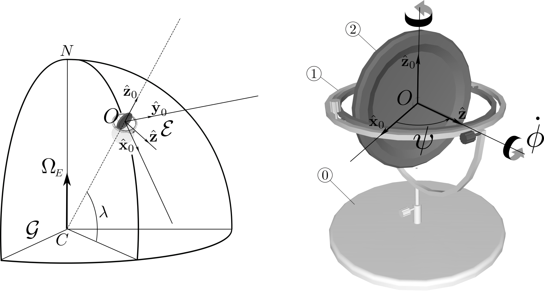
Example 2: Gyrocompass. A gyrocompass is a non-magnetic compass which is based on a fast-spinning axisymmetric suspended rotor and the rotation of the Earth to automatically find geographical direction. Gyrocompasses are widely used as a navigation tool on ships for their ability to find true north and for being unaffected by ferromagnetic materials. The gyrocompass is modeled as a system \(\Si\) consisting of a rotor
2 suspended by two gimbals. The rotation of the inner gimbal is blocked relative to the outer gimbal: the two rigidly connected gimbals, denoted 1, are allowed to rotate about a vertical axis \((O,\bz_0)\text{.}\)

The system \(\Si =\)
{1,2} is located at a point \(O\) of the Earth \(\cE(O, \bx_0,\by_0,\bz_0)\) at latitude \(\la\text{.}\) The Earth is assumed to rotate relative to the geocentric referential \(\cG\) at constant angular velocity \(\Om_E\text{.}\) The axis of the rotor \((O,\bz)\) lies in a horizontal plane \((O,\bx_0,\by_0)\) with axis \((O,\bx_0)\) pointing southward. Its orientation is defined by the angle \(\psi\) as follows
\begin{equation*}
(\bx_0,\by_0,\bz_0) \xrightarrow{\cR_{\psi , \, \bz_0}} (\bz,\bw,\bz_0)
\end{equation*}
The mass centers of both bodies
1 and 2 coincide with point \(O\text{.}\) The rotor is given a large angular velocity \(\dphi \bz\) about its axis so that its angular momentum about \(O\) (relative to \(\cE\)) can be approximated as \(C \dphi \bz\text{,}\) assuming \(\dphi\) a positive constant and denoting \(C\) the axial moment of inertia of the rotor. Denote by \(I_1\) the moment of inertia of body 1 about axis \((O,\bz_0)\text{.}\) Assume that all joints are frictionless.- Find the expression of the rate of change of the component \(\bz_0\cdot \bH_{O,\Si/\cG}\) of the system’s angular momentum about \(O\) relative to the geocentric referential \(\cG\text{.}\)
- Show that the axis of the rotor exhibits precessional oscillations about the equilibrium position \(\psi_e =\pi\text{.}\) Find the period of these oscillations. Conclude that, in the presence of friction, the axis points to the north.
Solution 2.
a. First we can relate the system’s angular momentum \(\bH_{O,\Si/\cG}\) relative to referential \(\cG\) to its angular momentum relative to \(\cE\text{:}\)
\begin{align*}
\bH_{O,\Si/\cG} \amp = \int_\Si \br_{OP}\times \vel_{P/\cG} dm =\int_\Si \br_{OP}\times (\vel_{P/\cE} + \vel_{P\in\cE/\cG}) dm \\
\amp = \bH_{O,\Si/\cE} + \int_\Si \br_{OP}\times R\Om_E\cos\la\, \by_0 \, dm = \bH_{O,\Si/\cE}
\end{align*}
where we have used the fact that \(O\) is the mass center of \(\Si\text{.}\) We then relate the rate of change of \(\bH_{O,\Si/\cG}\) relative to \(\cG\) to that relative to \(\cE\text{:}\)
\begin{equation*}
\left(\frac{d}{dt}\bH_{O,\Si/\cG}\right)_\cG = \left(\frac{d}{dt}\bH_{O,\Si/\cG}\right)_\cE + \bom_{\cE/\cG} \times
\bH_{O,\Si/\cG}
\end{equation*}
with
\begin{equation*}
\bH_{O,\Si/\cG} = \bH_{O,\Si/\cE} = \bH_{O,1/\cE} + \bH_{O,2/\cE} = I_1 \dpsi \bz_0 + C \dphi \bz
\end{equation*}
First we obtain \(\left(\frac{d}{dt}\bH_{O,\Si/\cG}\right)_\cE\text{:}\)
\begin{equation*}
\left(\frac{d}{dt}\bH_{O,\Si/\cG}\right)_\cE = \left(\frac{d}{dt} (I_1 \dpsi \bz_0 + C \dphi \bz) \right)_\cE
= I_1 \ddpsi \bz_0 + C \dphi \dpsi \bw
\end{equation*}
Next, we find \(\bom_{\cE/\cG} \times
\bH_{O,\Si/\cG}\text{:}\)
\begin{equation*}
\Om_E (-\cos\la \bx_0+ \sin\la \bz_0) \times (I_1 \dpsi \bz_0 + C \dphi \bz)
=\Om_E\cos\la (I_1 \dpsi \by_0- C \dphi \sin\psi\bz_0) + (\Om_E\sin\la) C \dphi \bw
\end{equation*}
The final expression is then given by
\begin{equation*}
\left(\frac{d}{dt}\bH_{O,\Si/\cG}\right)_\cG = (I_1 \ddpsi - C \Om_E\dphi \cos\la\sin\psi )\bz_0 +
(\Om_E\cos\la) I_1 \dpsi \by_0
+ (\Om_E\sin\la) C \dphi \bw \qquad{(1)}
\end{equation*}
b. We apply the dynamic moment equation of the FTD (Euler’s second principle) to system \(\Si\) relative to referential \(\cG\) (since \(\cE\) cannot be assumed Newtonian):
\begin{equation*}
\left(\frac{d}{dt}\bH_{O,\Si/\cG}\right)_\cG = \bM_{O,\bSi\to \Si}
\end{equation*}
Since \(O\) is the mass center of system \(\Si\) and the connection with the support
0 is frictionless, the external moment about \(O\) satisfies \(\bz_0 \cdot \bM_{O,\bSi\to \Si} =0\text{.}\) This leads to the equation, using (1)
\begin{equation*}
I_1 \ddpsi - C \Om_E\dphi\cos\la \sin\psi = 0 \qquad {(2)}
\end{equation*}
Two equilibrium positions are found: \(\psi =0\) (the axis points to the south) and \(\psi = \pi\) (the axis points to the north). The position \(\psi =0\) is unstable (note that \(\dphi >0\)). The position \(\psi =\pi\) is stable. The small amplitude oscillations about \(\psi= \pi\) are governed by
\begin{equation*}
I_1 \ddot{\ep} + (C \Om_E\dphi\cos\la) \ep = 0
\end{equation*}
with \(\ep= \psi -\pi\text{.}\) The corresponding period of these oscillations is given by
\begin{equation*}
T = 2\pi \sqrt{\frac{I_1}{C \Om_E \dphi\cos\la} }
\end{equation*}
With the presence of friction, we expect \(\bz_0 \cdot \bM_{O,\bSi\to \Si} \neq 0\) (proportional to \(\dpsi\) for viscous damping): the precessional oscillations will be dampened and the axis of the rotor will point toward the north.
