Problems 7.5 Problems

1.

A rectangular plate 1 of length \(2b\) and width \(2a\) moves relative to a referential 0 with the following constraints:
  1. corner point \(A\) moves along axis \(Ox\text{,}\)
  2. corner point \(B\) moves along axis \(Oy\text{,}\)
  3. its upper edge remains in contact with axis \(Oz\) at a point \(Q\text{.}\)
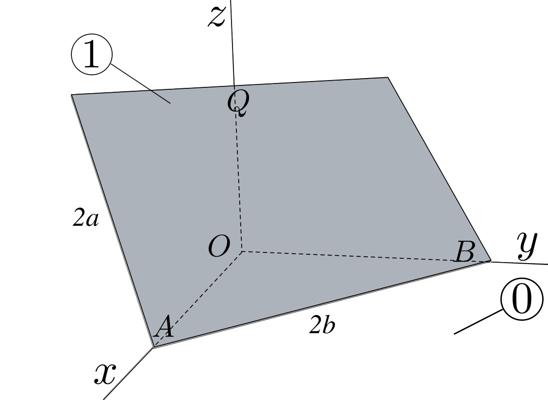
Figure 7.5.1.
  1. Find the kinematic screw \(\left\{{\cal V}_ {1/0} \right\}\) resolved at point \(Q\text{.}\) Identify all constraint equations.
  2. Find the angular acceleration \({\bal}_{1 / 0}\text{.}\)
Solution.
  1. We define two bases of unit vectors: \((\bx,\by,\bz)\) attached to referential 0, and \((\bi, \bj , \bk)\) attached to plate 1. The orientation of 1 relative to 0 is defined by the two angles \(\theta\) and \(\phi\text{.}\) The angle \(\theta\) defines the orientation of (right-handed) basis \((\bu , \bj , \bz)\) where \(\bj\) is directed along side \(AB\text{,}\) \(\bu\) is directed along \(OP\) perpendicular to \(AB\text{.}\) The angle \(\phi\) defines the orientation of \((\bi , \bk)\) relative to \((\bu , \bz)\text{:}\) \(\bk\) is directed along line \(PQ\text{,}\) \(\bi\) is perpendicular to the plate. See Figure 7.5.2.
    The quantities \(x, y, \phi\) can each be expressed in terms of angle \(\theta\text{.}\) With the diagrams shown in Figure 7.5.2 below, the vector loop equation
    \begin{equation*} \br_{OA}+ \br_{AP} + \br_{PQ} + \br_{QO} = \bze \end{equation*}
    yields 3 relationships (\(\br_{OA}= x \bx, \br_{AP}= \la \bj, \br_{PQ}= 2a \bk, \br_{OQ}=z\bz\)):
    \begin{equation*} x \cos\te = 2a \sin\phi, \quad \la = x \sin\te, \quad z= 2a \cos\phi \end{equation*}
    In addition we find 2 relationships in triangle \(OAB\text{:}\)
    \begin{equation*} \boxed{ x = 2b \sin\theta, \quad y = 2b \cos\theta, \quad 2a \sin \phi = 2b \sin\theta \cos\theta } \end{equation*}
    The last equation can also be found by expressing length \(|OP|= 2a \sin\phi \) (in triangle OQP), then \(|OP|= x \cos\theta\) (in triangle OAP).
    Figure 7.5.2.
    Then we find \(\bom _{1/0} = \dot{\te} \bz - \dot{\phi} \bj\) and \(\vel _{A/\cE} = \dot{x} \bx = 2b \dot{\te} \cos\te \bx\text{.}\) Hence,
    \begin{equation*} \{ {\cal V} _{1 / 0} \} = \left\{ \begin{array}{c} \dot{\te} \bz - \dot{\phi} \bj \\ 2b \dot{\te} \cos\te \bx \end{array} \right\}_A \end{equation*}
    To find velocity \(\vel_{Q \in 1/0}\text{,}\) we may use two methods:
    (i) we use the expression kinematic screw \(\{ {\cal V} _{1 / 0} \}\) to obtain \(\vel_{Q \in 1/0} = \vel_{A/0} + \bom _{1/0} \times \br_{AQ},\)
    (ii) we use the identity \(\vel_{Q\in 1/0}\) as the difference \(\vel_{Q/0}-\vel_{Q/1}\) with
    \begin{equation*} \vel_{Q/0}= d {\bf r}_{OQ}/ dt |_{0}= - 2a \dot{\phi} \sin\phi \bz \end{equation*}
    and
    \begin{equation*} \vel_{Q/1}= d {\bf r}_{AQ}/ dt |_{1}= 4b \dte\sin \te \cos\te\bj\text{.} \end{equation*}
    Both methods give
    \begin{equation*} \boxed{ \vel_{Q\in 1/0} = -4b \dte\sin \te \cos\te\bj - 2a \dot{\phi} \sin\phi \bz } \end{equation*}
  2. To find angular acceleration \({\bal}_{1 / 0}\text{,}\) we take the time-derivative of expression \(\dot{\te} \bz - \dot{\phi} \bj\) to find
    \begin{equation*} \boxed{ \bal_{1 / 0} = \ddte\bz - \ddot{\phi} \bj + \dte \dot{\phi} \bu } \end{equation*}
\(\blacksquare\)

2.

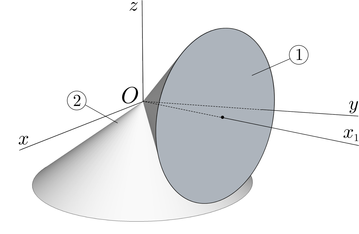
Two cones are in motion relative to a referential 0. Cone 2 rotates about axis \(Oz\) at constant rate \(\Omega_{2}\text{.}\) Cone 1 rolls without slipping on cone 2 so that its axis \(Ox_1\) rotates in the horizontal plane \(Oxy\) of 0 at constant rate \(\Omega_1\) about the vertical axis \(Oz\text{.}\) Let \(\gamma_1\) and \(\gamma_2\) be the vertex half-angle of 1 and 2, respectively.
Find the angular velocity and angular acceleration of cone 1 relative to referential 0. Determine the kinematic screws \(\left\{{\cal V}_ {1/0} \right\}\) and \(\left\{{\cal V}_ {1/2} \right\}\text{.}\)
Figure 7.5.3.
Solution.
Figure 7.5.4 shows a vertical cross section containing the cones’ axes and the contact line between the two cones.
We first define a basis \((\bx_{2},\by_{2},\bz )\) to cone 2. Its motion relative to referential 0 \((O, \bx ,\by ,\bz )\) is a rotation of axis \((O, \bz )\) and angle \(\Omega_{2} t\text{:}\)
\begin{equation*} \bom _{2 /0} = \Omega_{2} \bz \end{equation*}
Figure 7.5.4.
Then assign basis \((\bx_1 ,\by_{1},\bz_{1})\) to cone 1. See diagrams. Its motion relative to referential 0 is defined by the rotation of axis \((O, \bz )\) and angle \(\Omega_{1} t\) followed by the rotation of axis \((O, \bx_1)\) and angle \(\psi\text{:}\) \((O, \bx_1)\text{,}\) the axis of revolution of cone 1 remains in horizontal plane \((O, \bx, \by)\text{:}\)
\begin{equation*} \bom _{1 /0} = \Omega_{1} \bz + \dpsi \bx_1 \; . \end{equation*}
Call \(P\) a point on the contact line between cones 1 and 2 at a distance \(\lambda\) from vertex \(O\text{:}\)
\begin{equation*} \br_{OP}= \lambda ( \cos\gamma_1 \bx_1 - \sin\gamma_1 \bz) \end{equation*}
where the \(\gamma_1\) is the vertex half-angle of cone 1. Then write the no-slip condition at point \(P\) as
\begin{equation*} \vel_{P \in 1 /0} = \vel_{P \in 2 /0} \end{equation*}
with (using the fact that point \(O\) is a fixed point of both cones):
\begin{equation*} \vel_{P \in 1 /0} = \bom _{1 /0} \times \br_{OP} = (\Omega_{1} \bz + \dpsi \bx_1) \times \lambda ( \cos\gamma_1\bx_1 - \sin\gamma_1 \bz ) = \lambda \cos\gamma_1 ( \Omega_{1} + \dpsi\tan\gamma_1 ) \bv \end{equation*}
and
\begin{equation*} \vel_{P \in 2 /0} = \bom _{2 /0} \times \br_{OP} = \Omega_2 \bz \times \lambda ( \cos\gamma_1\bx_1 - \sin\gamma_1 \bz ) = \lambda \cos\gamma_1 \Omega_{2} \bv \end{equation*}
Equate these two expressions to find
\begin{equation*} \boxed{\Omega_{1} + \dpsi\tan\gamma_1 = \Omega_{2} } \end{equation*}
which yields the expression for \(\dpsi\) (independent of \(\lambda\)). The kinematic screw of body 1 relative to body 2 is found as
\begin{equation*} \{ {\cal V} _{1 / 2} \} = \{ {\cal V} _{1 / 0} \}- \{ {\cal V} _{2 / 0} \} = \left\{ \begin{array}{c} \Omega_{1} \bz + \dpsi \bx_1 \\ \bze \end{array} \right\}_O - \left\{ \begin{array}{c} \Omega_{2} \bz \\ \bze \end{array} \right\}_O = \left\{ \begin{array}{c} (\Omega_{1}-\Omega_{2})(\bz - \cot\gamma_1 \bx_1) \\ \bze \end{array} \right\}_O \end{equation*}
We verify that the angular velocity \(\bom_{1/2}\) takes the direction of the contact line between the two cones. The contact line is indeed the instantaneous axis of rotation \(\Delta_{1/2}\text{.}\)
The angular acceleration of cone 1 is
\begin{equation*} \bal _{1/0} = \ddpsi \bx_1 + \Omega_{1}\dpsi \bv \end{equation*}
If \(\Omega_{1}\) and \(\Omega_{2}\) are constant in time, then \(\dpsi\) is also constant,
\begin{equation*} \boxed{\bal _{1 /0} = \Omega_1\dpsi \bv} \end{equation*}
\(\blacksquare\)

3.

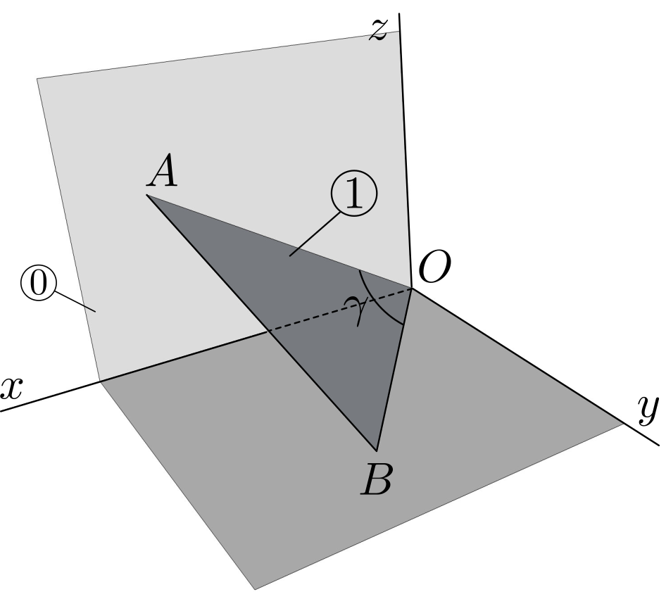
A triangular plate 1 of vertices \(O\text{,}\) \(A\text{,}\) and \(B\) moves in a referential 0 in such a way that
  1. vertex \(O\) remains fixed,
  2. vertex \(A\) is constrained to move in plane \(Oxz\text{,}\)
  3. vertex \(B\) is constrained to move in plane \(Oxy\text{.}\)
Figure 7.5.5.
Find the kinematic screw \(\left\{{\cal V}_ {1/0} \right\}\) and the corresponding instantaneous screw axis. Assume \(|OA| = |OB| = a\text{,}\) and denote by \(\gamma\) the angle at \(O\text{.}\)
Solution.
The most natural way to parametrize the position of body 1 is to introduce angle \(\te = (\be_x , \bu)\) to define the orientation of line \(OB\) and angle \(\phi = (\be_z , \bw)\) to define the position of line \(OA\text{.}\) Unit vectors \(\bu\) and \(\bw\) are such that \(\br_{OB} = a \bu\text{,}\) and \(\br_{OA} = a \bw\text{.}\) Then define \(\bv = \be_z \times \bu\) and \(\bx = \be_y \times \bw\text{.}\) Clearly we cannot write \(\bom_{1/0} = \dte \be_z + \dphi \be_y\text{.}\) We find the angular velocity \(\bom_{1/0}\) of body 1 from the knowledge of \(\vel_A\) and \(\vel_B\text{.}\)
Since \(B\) remains in plane \(Oxy\) at a constant distance from \(O\text{,}\) we have \(\vel_B = a \dte \bv = \bom_{1/0} \times a \bu\) which leads to
\begin{equation*} \bom_{1/0} = \dte \be_z + \om_u \bu \qquad{(1)} \end{equation*}
with the component \(\om_u\) yet to be determined.
Figure 7.5.6.
Since \(A\) remains in plane \(Oxz\) at a constant distance from \(O\text{,}\) we have \(\vel_A = a \dphi \bx = \bom\times a \bw\) which leads to
\begin{equation*} \bom_{1/0} = \dphi \be_y + \om_w \bw \qquad{(2)} \end{equation*}
where the component \(\om_w\) is still unknown. Now compare equations (1) and (2): \(\dte \be_z + \om_u \bu = \dphi \be_y + \om_w \bw\) gives
\begin{equation*} \om_u = \frac{\dphi}{\sin\te} \end{equation*}
Finally
\begin{equation*} \boxed{\bom_{1/0} = \dte \be_z + \frac{\dphi}{\sin\te} \bu} \end{equation*}
Of course the angle \(\te\) and \(\phi\) are not independent: \(\bu\cdot\bw = \cos\gamma\text{,}\) leading to the geometric constraint equation
\begin{equation*} \boxed{\sin\phi \cos\te = \cos\gamma} \end{equation*}
and by differentiation
\begin{equation*} \dphi = \dte \tan\phi \tan\te \end{equation*}
We conclude with the expression of the kinematic screw of body 1
\begin{equation*} \{ {\cal V} _{1 /0} \} = \left\{ \begin{array}{c} \dte \be_z + {\dphi \over \sin\te} \bu \\\\ \bze \end{array} \right\}_O \end{equation*}
\(\blacksquare\)

4.

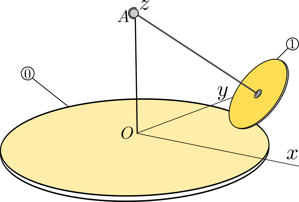
Consider a rigid body 1 consisting of a disk of center \(C\) and radius \(r\) rigidly connected to a rod \(AC\) of length \(l\) coinciding with the axis of the disk. Body 1 is set in motion in a referential 0 in such a way that extremity \(A\) remains fixed on axis \(Oz\) of 0 and that the disk stays in contact with fixed support \(Oxy\text{.}\) Denote by \(h\) the distance from \(O\) to \(A\text{.}\) The angular velocity of plane \(OAC\) about the vertical axis \(Oz\) is imposed to be \(\Omega\text{.}\)
Determine the angular velocity \(\bom_{1/0}\) of the disk in terms of \(\Omega\text{,}\) \(h\text{,}\) \(r\) and \(l\text{,}\) assuming no-slip at the contact point.
Figure 7.5.7.

5.

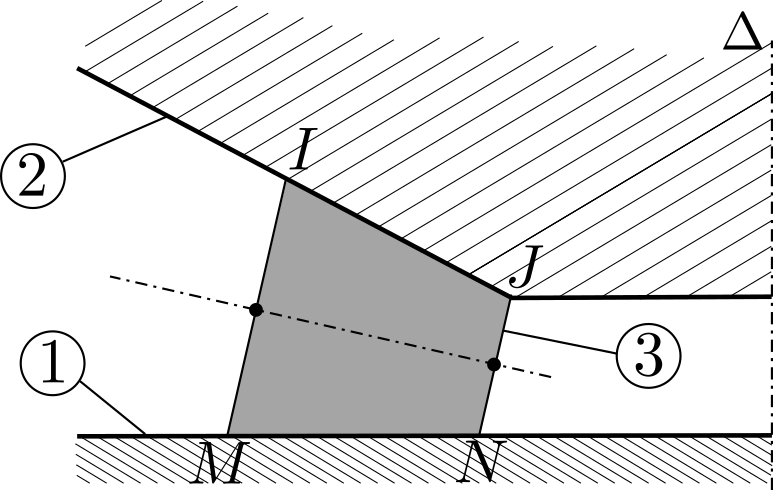
In order to facilitate the rotation between two rigid bodies 1 and 2 about the same axis \(\Delta\) of some referential 0, one can interpose truncated cones 3 between them in such a way that contact is achieved along line segments \(MN\) of 1 and \(IJ\) of 2.
Determine the geometric condition which guarantees the no-slip condition along both contact lines. Find the relationship between the angular velocities \(\bom_{3/0}\text{,}\) \(\bom_{2 /0}\text{,}\) \(\bom_{1/0}\) of bodies 3, 2 and 1 relative to referential 0 when no slip is achieved.
Figure 7.5.8.
Solution.
Denote by \((\bu , \bv =\be_z\times \bu , \be_z)\) a basis of unit vectors attached to body 1 which is in rotation about axis \((O, \be_z)\text{:}\) \(\bom_{1 /0} = \om_1 \be_z\text{.}\) For any point \(P\) of the line segment \(MN\) we have \(\vel_{P\in 1/0} = \om_1 \be_z \times \br_{OP} = \la \om_1 \bv\) with \(\br_{OP}= \la\bu\text{.}\)
Figure 7.5.9.
The motion of body 3 relative to 0 consists of a rotation about \((O, \be_z)\) followed by a rotation about its axis of revolution \((C, \bw)\text{:}\) its angular velocity can be written as \(\bom_{3/0} = \dphi \be_z + \dpsi \bw\text{.}\) For any point \(P\) of the line segment \(MN\) we have \(\vel_{P\in 3/0} = \vel_{C/0} + \bom_{3/0} \times \br_{CP}\text{.}\) Denote by \((a,h)\) the scalars defining the position of point \(C\) (an arbitrary point on the axis of body 3): \(\br_{OC}= a\bu+ h\be_z\text{.}\) Then \(\vel_{C/0} = a \dphi \bv\text{,}\) which gives \(\vel_{P\in 3/0} = a\dphi \bv + (\dphi \be_z + \dpsi \bw)\times (\la \bu - a\bu- h\be_z)\text{.}\)
The no-slip condition of body 3 relative to body 1 is expressed by the condition \(\vel_{P\in 1/0}=\vel_{P\in 3/0}\) for all \(P\) on line segment \(MN\text{:}\)
\begin{equation*} \la (\dphi + \dphi\sin\al -\om_1) + \dpsi(h\cos\al-a\sin\al)=0 \end{equation*}
denoting \(\al\) the (constant) angle \((\bu, \bw)\text{.}\) Since \(\la\) is arbitrary, this leads to the two conditions
\begin{equation*} \boxed{ h/a = \tan\al , \qquad \dphi + \dphi\sin\al =\om_1 } \end{equation*}
The equation \(h/a = \tan\al\) expresses the condition for axis \((C,\bw)\) to pass through point \(O\text{.}\) Since \((\bw, \bw_2) = \al\text{,}\) line \(IJ\) will also pass through \(O\text{.}\)
Denote by \(\bom_{2 /0} = \om_2 \be_z\text{.}\) Then for any point on line segment \(IJ\) defined by \(\br_{OQ} = \mu\bw_2\text{,}\) \(\vel_{Q\in 2/0} =\om_2 \be_z \times \mu\bw_2 = \mu\om_2 \cos 2\al \bv\text{.}\) If the same point is considered a point of body 3, then its velocity is given by \(\vel_{Q\in 3/0}= (\dphi \be_z + \dpsi \bw) \times \mu\bw_2 = \mu (\dphi \cos2\al - \dpsi\sin\al)\bv\text{.}\) The no-slip condition of body 2 relative to body 1 is expressed by the condition \(\vel_{P\in 2/0}=\vel_{P\in 3/0}\) for all \(Q\) on line segment \(IJ\text{:}\)
\begin{equation*} \boxed{\om_2 \cos2\al = \dphi \cos 2\al - \dpsi\sin\al} \end{equation*}
We have obtained two relationships between the angular velocities \(\om_1\text{,}\) \(\om_2\text{,}\) \(\dphi\) and \(\dpsi\text{.}\) If \(\om_1\) and \(\om_2\) are imposed then \(\om_{3/0}\) is known.
\(\blacksquare\)