MEEG 681 / MEEG481
Computer Solution of Engineering Problems
Computer Session 7
In this session we solve an unsteady water flow around a two-dimensional
cylinder using FIDAP.
Step-by-Step FIDAP Instructions for Setting up the
model
1. Starting the FID AP GUI:
cd /tmp
mkdir mydir (make a new directory)
cd mydir (Always start in a new, empty directory)
fidap -id 2Dcyld -gui (start a FIDAP session named 2Dcyld)
click the "FIDAP version window" to remove it
2. Start up FI-GEN (the mesh generation module):
-
Click FI-GEN
-
Click Accept (after a few seconds a graphical window appears)
3. Generating the Geometry (i.e., Points, Curves and Surfaces):
-
select Point
-
click Add under COMMAND OPTION
-
Enter the coordinates of the following 7 points: (0,0), (10,0), (10,5),
(0,5), (2.0,2.5), (2.5,2.0), (3.0,2.5) (will be referred to as points 1,
2, 3, 4, 5, 6, 7 in this order)
-
Move the cursor into the graphical window and type the letter "F" to bring
all the 7 points into the window (you should see all the 7 points, each
marked by a plus sign)
-
Click Curve (1)
-
Select ADD Line under COMMAND OPTION
-
Left click the points 1-2-3-4-1 in order in the graphical window, and then
right click
-
Select Curve(2)
-
click ADD circle
-
Left click points 5, 6, and 7, then right click (a circle is drawn)
-
Select Surface
-
Click ADD by W/F
-
Left click the 4 lines connecting the points 1-2, 2-3, 3-4, 4-1 in order,
then right click
4. Creating mesh:
-
Click Mesh Edge , Select ADD
-
Input 25 in the "Interval" box field
-
Left click the two vertical lines connecting the points 4-1,2-3;
-
Right click (you should see 26 nodes on each of the vertical line)
-
Input 40 in the "Interval" box field
-
Left click the two horizontal lines connecting the points 1-2,3-4; then
right-click
-
Input 20 in the "Interval" box field
-
Left click the circle, Right click
-
Select Mesh Loop , click Add Pave
-
Left click the 4 lines connecting the points 1-2, 2-3, 3-4, 4-1 in order,
then right click
-
Left click the circle, then right click
-
Select Mesh Face, click ADD
-
left-click on the dark blue surface cross bar, right-click
-
left-click on the outside square, then left-click on the inner circle,
right-click
-
Select Bndry Edge , click Add
-
Select Layers under BOUNDARY EDGE DEFAULTS
-
Input 0.2 in the Height 1 field, 1.1 in the Growth factor field, and 3
in the No. Layer field
-
left-click on the mesh face boundary, right click
-
left-click on the circle, right click (You should see Be mark near the
circle)
-
Select Mesh Face, click Mesh
-
Click "All" under SELECT OPTION
-
Click "Pave" under MESH FACE DEFAULTS
-
Input "fluid" in the "Entity" box
-
Right click in the graphical window (Now mesh is being generated, this
may take a few minutes)
5. Specifying entity names for the boundaries:
-
Click Mesh Edge
-
Select MESH MAP
-
Left click the line connecting points 1 and 2
-
Input "bottom" in the "Entity" field
-
Right click in the graphical window
-
Left click the line connecting points 3 and 4
-
Input "top" in the "Entity" field
-
Right click in the graphical window
-
Left click the lines connecting points 4-1
-
Input "inlet" in the "Entity" field
-
Right click in the graphical window
-
Left click the lines connecting points 2-3
-
Input "outlet" in the "Entity" field
-
Right click in the graphical window
-
Left click the cylinder
-
Input "cylinder" in the "Entity" field
-
Right click in the graphical window
-
Click END once to exit FIGEN
6. Defining entity labels
-
Click FIPREP, Select "Entity"
-
Left click the question mark to select "fluid" entity
-
Input "Fluid" in the ENTITY TYPE field, Right click ADD-ADD (REPEAT)
-
Left click the question mark to select "bottom" entity
-
Input "plot" in the ENTITY TYPE field, Right click ADD-ADD (REPEAT)
-
Repeat this for the other boundary entities: "top", "inlet", "outlet",
"cylinder".
7. Specifying fluid properties
-
Click Properties
-
Click "DENSITY"
-
Input 0.998 in the MODEL TYPE-CONSTANT field
-
Click ADD
-
Click "VISCOSITY"
-
Input 0.01003 in the MODEL TYPE-CONSTANT field
-
Click ADD
8. Specifying boundary conditions
-
Click Boundary C., Click BCNODE
-
Right-click exclamation point next to DEGREE of FREEDON, Pick VELOCITY
-
Right-click exclamation point next to REGION SELECTION, Pick ENTITY
-
Left-click question mark beside REGION SELECTION field, Pick "cylinder"
-
Right-click exclamation point next to VALUE GENERATION field, Pick Zero
-
Right-select ADD(REPEAT)
-
Right-click exclamation point next to DEGREE of FREEDON
-
Pick UX
-
Left-click question mark beside REGION SELECTION field, Pick "inlet"
-
Right-click exclamation point next to VALUE GENERATION field
-
Set CONST ANT to 1.0
-
Right-select ADD(REPEAT)
-
Right-click exclamation point next to DEGREE of FREEDON
-
Pick UY
-
Left-click question mark beside REGION SELECTION field, Pick "inlet"
-
Right-click exclamation point next to VALUE GENERATION field
-
Pick Zero, Right-select ADD (REPEAT)
-
Left-click question mark beside REGION SELECTION field, Pick "top"
-
Right-click exclamation point next to VALUE GENERATION field
-
Pick Zero, Right-select ADD(REPEAT)
-
Left-click question mark beside REGION SELECTION field, Pick "bottom"
-
Right-click exclamation point next to VALUE GENERATION field
-
Pick Zero, Right-select ADD
9. Specifying the problem type
-
Select Simulation
-
Click EXECUTION
-
Change EXECUTION MODE to NEWJOB
-
Click ADD
-
Click PROBLEM
-
Change SIMULATION TYPE to TRANSIENT
-
Change CONVECTIVE TERM to NONLINEAR
-
Click ADD
-
Click TIMEINTEGRATION
-
Set NSTEPS=60
-
Set TSTART=0.0
-
Set DT=0.05
-
Click ADD
-
Click END to exit FIPREP
10. Creating the Database
-
Click CREATE
-
Select Create
-
Click ACCEPT
11. Solving the problem
-
Click RUN
-
Pick FISOLV
-
Pick FOREGROUND
-
Click ACCEPT (Now relax and wait for the simulation to finish, this may
take a minute or two)
12. Get ready for post processing
-
Click IDENT
-
Click ACCEPT
-
Click FIPOST
-
Click ACCEPT
13. Visualizing the vector velocity field
-
Click Vector
-
Click Accept
14. Plotting streamlines
-
Click Utility
-
Select TIMESTEP
-
Set to desired time step, click ADD
-
Click Contour
-
Right-click exclamation point next to DEGREE of FREEDON
-
Pick STREAMLINE
-
Input 60 in the CONTOUR LEVELS-AUTOMATIC field (this will draw 60 contour
levels in stead of 10 by default).
-
Click ACCEPT (You can clearly see the re-circulation region)
15. Plot and read results on a line
-
PLOT-LINE: Degree of freedom = UX, LINE DEFINITION=PVECTOR, ACCEPT
-
INPUT: 0.,2.5,0.0,1.,0.0,0.0
-
Also check the results in the *.FIOUT file
16. Compute drag force on cylinder
- Go to FIPOST
- Computation - STRSPRINT - Stress Type=Total, Sides definition =Entity.Cylinder, Accept
- In the History window, the X Total Force is the drag.
17. Exit FIDAP (always remember to exit FIDAP properly)
-
Click END to exit FIPOST
-
Click END one more time to exit FIDAP
-
Answer YES to the EXIT PROMPT question
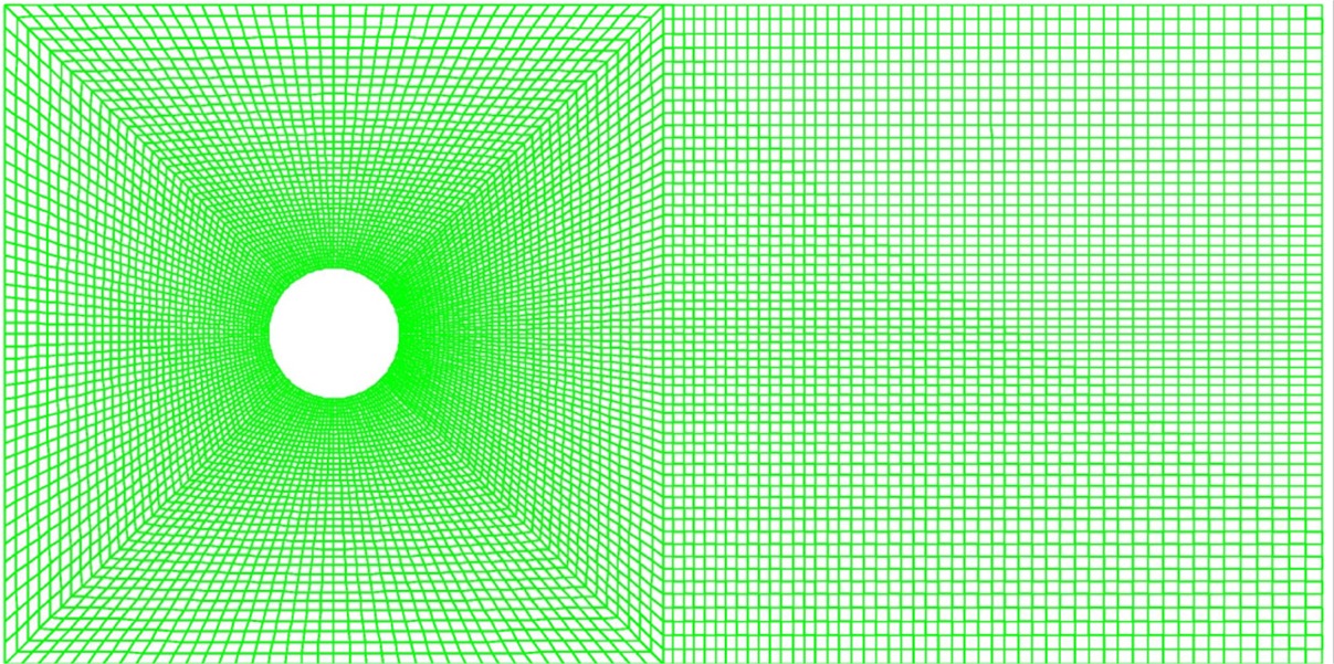
Using Gambit to model the problem with a different mesh
/ Journal File for GAMBIT 1.3.0
/ File opened for write Wed Apr  4 11:19:03 2001.
identifier name "cylind" new saveprevious
undo begingroup
vertex create coordinates 0 0 0
undo endgroup
undo begingroup
vertex create coordinates 5 0 0
undo endgroup
undo begingroup
vertex create coordinates 10 0 0
undo endgroup
undo begingroup
vertex create coordinates 10 5 0
undo endgroup
undo begingroup
vertex create coordinates 5 5 0
undo endgroup
undo begingroup
vertex create coordinates 0 5 0
undo endgroup
undo begingroup
/
vertex create coordinates 2.5 2.510 0
/ This introduce a little bit of asymmetry to the domain to help generate
/ vortex shedding
/
undo endgroup
edge create radius 0.5 startangle 45 endangle 135 center "vertex.7" xyplane arc
edge create radius 0.5 startangle 135 endangle 225 center "vertex.7" xyplane arc
edge create radius 0.5 startangle 225 endangle 315 center "vertex.7" xyplane arc
edge create radius 0.5 startangle 315 endangle 45 center "vertex.7" xyplane arc
vertex connect "vertex.1" "vertex.2" "vertex.3" "vertex.4" "vertex.5" \
  "vertex.6" "vertex.7" "vertex.8" "vertex.9" "vertex.10" "vertex.11" \
  "vertex.12" "vertex.13" "vertex.14" "vertex.15" real
edge create straight "vertex.1" "vertex.2" "vertex.3" "vertex.4" "vertex.5" \
  "vertex.6"
edge create straight "vertex.6" "vertex.1"
edge create straight "vertex.5" "vertex.2"
edge create straight "vertex.6" "vertex.9"
edge create straight "vertex.5" "vertex.8"
edge create straight "vertex.2" "vertex.13"
edge create straight "vertex.11" "vertex.1"
face create wireframe "edge.10" "edge.15" "edge.2" "edge.12" real
face create wireframe "edge.12" "edge.1" "edge.13" "edge.9" real
face create wireframe "edge.4" "edge.14" "edge.11" "edge.13" real
face create wireframe "edge.14" "edge.3" "edge.15" "edge.5" real
face create wireframe "edge.6" "edge.7" "edge.8" "edge.11" real
undo begingroup
edge picklink "edge.10"
edge mesh "edge.10" successive ratio1 0.97 ratio2 0.97 intervals 40
undo endgroup
undo begingroup
edge picklink "edge.11" "edge.7"
edge mesh "edge.7" "edge.11" successive ratio1 0.98 ratio2 0.98 intervals 60
undo endgroup
undo begingroup
edge picklink "edge.4"
edge mesh "edge.4" successive ratio1 0.99 ratio2 0.99 intervals 60
undo endgroup
undo begingroup
edge picklink "edge.3" "edge.2" "edge.1"
edge mesh "edge.1" "edge.2" "edge.3" successive ratio1 1 intervals 40
undo endgroup
undo begingroup
edge picklink "edge.12"
edge mesh "edge.12" successive ratio1 0.97 intervals 40
undo endgroup
undo begingroup
edge picklink "edge.13"
edge mesh "edge.13" successive ratio1 0.97 intervals 40
undo endgroup
undo begingroup
edge picklink "edge.15"
edge mesh "edge.15" successive ratio1 1.03093 intervals 40
undo endgroup
undo begingroup
edge picklink "edge.14"
edge mesh "edge.14" successive ratio1 0.97 intervals 40
undo endgroup
undo begingroup
edge picklink "edge.5" "edge.9"
edge mesh "edge.9" "edge.5" successive ratio1 1 intervals 40
undo endgroup
undo begingroup
edge picklink "edge.6" "edge.8"
edge mesh "edge.8" "edge.6" successive ratio1 1 intervals 40
undo endgroup
face mesh "face.1" "face.2" "face.3" "face.4" "face.5" map size 1
face delete "face.5" onlymesh
undo begingroup
edge delete "edge.8" keepsettings onlymesh
edge mesh "edge.8" successive ratio1 0.99 intervals 50
undo endgroup
undo begingroup
edge delete "edge.6" keepsettings onlymesh
edge mesh "edge.6" successive ratio1 1.0101 intervals 50
undo endgroup
face mesh "face.5" map size 1
solver select "FIDAP"
physics create "fluid" ctype "FLUID" face "face.1" "face.2" "face.3" "face.4" \
  "face.5"
physics create "inlet" btype "PLOT" edge "edge.10"
physics create "top" btype "PLOT" edge "edge.9" "edge.8"
physics create "bottom" btype "PLOT" edge "edge.5" "edge.6"
physics create "outlet" btype "PLOT" edge "edge.7"
physics create "cylinder" btype "PLOT" edge "edge.4" "edge.1" "edge.2" \
  "edge.3"
export fidap "cylind.FDNEUT"
/ File closed at Wed Apr  4 11:53:02 2001, 15.56 cpu second(s), 4840040 maximum memory.
FIPREP file for the unsteady case
/
/          CONVERSION OF NEUTRAL FILE TO FIDAP Database
/
FICONV( NEUTRAL )
INPUT( FILE="cylind.FDNEUT" )
OUTPUT( DELETE )
END
/
/
TITLE
cylind
/
FIPREP(  )
/
EXECUTION( ADD, NEWJ )
/
PROBLEM( ADD, 2-D, INCO, TRAN, LAMI, NONL, NEWT, MOME, ISOT, FIXE, SING )
/
/ TIMEINTEGRATION( ADD, BACK, NSTE = 201, TSTA = 0, DT = 0.25, FIXE )
/ TIMEINTEGRATION( ADD, BACK, NSTE = 201, TSTA = 50.25, DT = 0.25, FIXE )
TIMEINTEGRATION( ADD, BACK, NSTE = 401, TSTA = 100.50, DT = 0.25, FIXE )
SOLUTION( S.S. = 50, VELCONV = .001, RESCONV = .001)
/
POSTPROCESS(NBLOCKS=1)
1 401 4
/
DATAPRINT( ADD, CONT )
PRINTOUT( ADD, NONE, BOUN )
/
ENTITY( ADD, NAME = "fluid", FLUI )
ENTITY( ADD, NAME = "bottom", PLOT )
ENTITY( ADD, NAME = "top", PLOT )
ENTITY( ADD, NAME = "inlet", PLOT )
ENTITY( ADD, NAME = "outlet", PLOT )
ENTITY( ADD, NAME = "cylinder", PLOT )
/
DENSITY( ADD, SET = 1, CONS = 0.998 )
VISCOSITY( ADD, SET = 1, CONS = 0.01003 )
/
/ ICNODE( ADD, VELO, ZERO, ENTI = "fluid", X, Y, Z )
/ To read steady-state flow field as the initial condition:
/ change *.FDPOST to *.FDREST
/ and then
ICNO (VELO, READ)
/
BCNODE( ADD, VELO, ENTI = "cylinder", ZERO, X, Y, Z )
BCNODE( ADD, UY, ENTI = "inlet", ZERO )
BCNODE( ADD, UX, ENTI = "inlet", CONS = 1.00 )
BCNODE( ADD, UY, ENTI = "bottom", ZERO )
BCNODE( ADD, UY, ENTI = "top", ZERO )
/
END(  )
CPU TIME for the runs on mahler:
First 201 steps: 6528 s
Next 201 steps: 20398 s
Next 401 steps: 40496 s
Print a hard copy of FIPOST visualizations
-
Click Graphics
-
Click Device
-
Select Postscript as Device driver, then Accept
-
Run FIPOST (all the plots are now saved in a file 2Dbed.FIPLOT)
-
Exit FIDAP
-
fdp2ps
-
Enter 2Dbed.FIPLOT as plot file
-
Name the postscript file as you like
Results for unsteady simulations
Re = 100 (Spring 2001)
Re = 200 (Spring 2002)
How to start a run with initial field specified as the last field of a previous run?
/ change *.FDPOST to *.FDREST
/ and then
ICNO (VELO, READ)
/