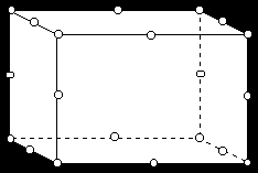
This work session illustrates how to use ANSYS to analyze three-dimensional solid deformation.

The Connecting Lug
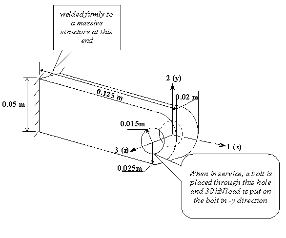
(Note: 30 kN vertical load is replaced by a pressure distribution of 50 MPa over the bottom half of the hole.)
Find: the deflection and stress distribution in the lug .
Element configuration on x-y plane
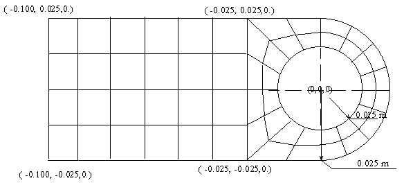
Plus two uniform intervals in the z direction.
The linear elastic model:
Steel as material: Young's Modulus E=200 GPa and Poisson
Ratio u = 0.3
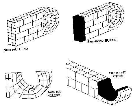
The procedure for building the model
The procedure for building the model for the connecting lug
STEP 1
======
 Preferences for GUI filtering have been set to display:
   Structural

STEP 2:
======
ELEMENT TYPE      1 IS SOLID95      20-NODE STRUCTURAL SOLID
  KEYOPT(1-12)=    0  0  0    0  0  0    0  0  0    0  0  0

 CURRENT NODAL DOF SET IS  UX    UY    UZ
  THREE-DIMENSIONAL MODEL

STEP 3:
=======
 MATERIAL         1     EX   =  0.2000000E+13

 MATERIAL         1     NUXY =  0.3000000

STEP 4: GEOMETRY SET-UP
STEP 4a:
========
Create>Volume>By dimension

 CREATE A HEXAHEDRAL VOLUME WITH
 X-DISTANCES FROM     -10.00000000     TO     -2.500000000
 Y-DISTANCES FROM               0.     TO      2.500000000
 Z-DISTANCES FROM               0.     TO      2.000000000

      OUTPUT VOLUME =     1

 PLOT VOLUMES FROM     1  TO     1  BY    1

STEP 4b:
========
Create>Cylinder>Partial Cylinder
(depth=2)
 CREATE A CYLINDRICAL VOLUME WITH
 INNER RADIUS         =      1.500000000
 OUTER RADIUS         =      2.500000000
 STARTING THETA ANGLE =               0.
 ENDING   THETA ANGLE =      90.00000000
 END Z-DISTANCES FROM                 0.     TO      2.000000000

      OUTPUT VOLUME =     2

 PLOT VOLUMES FROM     1  TO     2  BY    1

STEP 4c:
========
 ADJUST THE VIEW ANGLE
 PLOT LINES FROM     1:  TO    24  BY      1

STEP 4d:
========
Create an arc containing two lines  By Center & Radius: Input: (0.,0.) (0.,1.5), 90, 2  (note the last input denotes two equal lines)

  LINE NO.=    25  KP1=     17  TAN1=    1.0000   0.0000   0.0000
                   KP2=     18  TAN2=   -0.7071  -0.7071   0.0000
  LINE NO.=    26  KP1=     18  TAN1=    0.7071   0.7071   0.0000
                   KP2=     19  TAN2=    0.0000  -1.0000   0.0000

STEP 4e:
Operate>Glue>Lines
 GLUE LINES
      INPUT LINES =    14   25
      INPUT LINES WILL BE DELETED
      OUTPUT LINES =    14   27

 PLOT LINES FROM     1  TO    27  BY      1

STEP 4f:
Create>Lines>Straight lines

LINE CONNECTS KEYPOINTS      4    19
  LINE NO.=    25  KP1=      4  TAN1=   -1.0000   0.0000   0.0000
                   KP2=     19  TAN2=    1.0000   0.0000   0.0000

 LINE CONNECTS KEYPOINTS      3    12
  LINE NO.=    28  KP1=      3  TAN1=   -1.0000   0.0000   0.0000
                   KP2=     12  TAN2=    1.0000   0.0000   0.0000

 LINE CONNECTS KEYPOINTS     18     3
  LINE NO.=    29  KP1=     18  TAN1=    0.7071  -0.7071   0.0000
                   KP2=      3  TAN2=   -0.7071   0.7071   0.0000


STEP 4g:
Create>areas>Arbitrary>By lines
 DEFINE AREA BY LIST OF LINES
      (TRAVERSED IN SAME DIRECTION AS LINE    27)

     AREA NUMBER =     13

 DEFINE AREA BY LIST OF LINES
      (TRAVERSED IN SAME DIRECTION AS LINE    25)

     AREA NUMBER =     14

STEP 4f:
========
Operate>Extrude>Areas/Along lines
DRAG AREAS
         13,
      ALONG LINES
         21,

 PLOT VOLUMES FROM     1  TO     3  BY    1


 DRAG AREAS
         14,
      ALONG LINES
         10,


STEP 4g: This step is needed to eliminate the redundant key points etc.
========
Operate>Glue>Volume
 GLUE VOLUMES
      INPUT VOLUMES =     1    2    3    4
      INPUT VOLUMES WILL BE DELETED
      OUTPUT VOLUMES =     1    2    5    6

 PLOT VOLUMES FROM     1  TO     6  BY    1

STEP 4h:
========
Modeling>reflect>Volumes, wrt xz plane

 SYMMETRY TRANSFORMATION OF VOLUMES       USING COMPONENT  Y
   SET IS FROM PICKED ENTITIES

 PLOT VOLUMES FROM     1  TO     8  BY    1

STEP 4i:
========
Operate>Glue>volume
 GLUE VOLUMES
      INPUT VOLUMES =     1    2    3    4    5    6    7    8
      INPUT VOLUMES WILL BE DELETED
      OUTPUT VOLUMES =     1    2    5    6    8    9   10   11

 PLOT VOLUMES FROM     1  TO    11  BY    1

Plot>Specified Entities/Volume

 PLOT VOLUMES FROM     1  TO     1  BY    1

STEP 4j: Volume 1 is being meshed...

Mesh Tool>Line Set
 SET DIVISIONS ON ALL PICKED UNMESHED LINES
      TO  NDIV =    6,  SPACING RATIO =   1.000

 SET DIVISIONS ON ALL PICKED UNMESHED LINES
      TO  NDIV =    2,  SPACING RATIO =   1.000

Mesh Tool>Mesh, Volume, Hex, Map

 PRODUCE ALL HEXAHEDRAL ELEMENTS IN 3D.
 USE THE MAPPED MESHER.

 GENERATE NODES AND ELEMENTS   IN  ALL  PICKED   VOLUMES

 Initiating meshing of volume 1 exterior.

 Meshing of volume 1 exterior is complete.  Facet count = 56.

 Initiating meshing of volume 1 interior.
  Estimated number of elements to fill this volume = 24.
  Estimated number of nodes = 325.

 Meshing of volume 1 is complete.
  Now storing 31 nodes and 24 elements.

 NUMBER OF VOLUMES MESHED   =       1
 MAXIMUM NODE NUMBER        =     201
 MAXIMUM ELEMENT NUMBER     =      24

 PRODUCE ELEMENT PLOT IN DSYS =   0

STEP 4k: Volume 2 is being meshed....
=======

 PLOT VOLUMES FROM     2  TO     2  BY    1

 SET DIVISIONS ON ALL PICKED UNMESHED LINES
      TO  NDIV =    4,  SPACING RATIO =   1.000

 SET DIVISIONS ON ALL PICKED UNMESHED LINES
      TO  NDIV =    2,  SPACING RATIO =   1.000

 GENERATE NODES AND ELEMENTS   IN  ALL  PICKED   VOLUMES

 Initiating meshing of volume 2 exterior.

 Meshing of volume 2 exterior is complete.  Facet count = 40.

 Initiating meshing of volume 2 interior.
  Estimated number of elements to fill this volume = 16.
  Estimated number of nodes = 225.

 Meshing of volume 2 is complete.
  Now storing 19 nodes and 16 elements.

 NUMBER OF VOLUMES MESHED   =       1
 MAXIMUM NODE NUMBER        =     342
 MAXIMUM ELEMENT NUMBER     =      40

 PRODUCE ELEMENT PLOT IN DSYS =   0

STEP 4L: Volume 5 is being meshed....
======

PLOT VOLUMES FROM     3  TO     5  BY    1

 SET DIVISIONS ON ALL PICKED UNMESHED LINES
      TO  NDIV =    2,  SPACING RATIO =   1.000

 GENERATE NODES AND ELEMENTS   IN  ALL  PICKED   VOLUMES

 Initiating meshing of volume 5 exterior.

 Meshing of volume 5 exterior is complete.  Facet count = 24.

 Initiating meshing of volume 5 interior.
  Estimated number of elements to fill this volume = 8.
  Estimated number of nodes = 125.

 Meshing of volume 5 is complete.
  Now storing 7 nodes and 8 elements.

 NUMBER OF VOLUMES MESHED   =       1
 MAXIMUM NODE NUMBER        =     402
 MAXIMUM ELEMENT NUMBER     =      48

 PRODUCE ELEMENT PLOT IN DSYS =   0


STEP 4m: Volume 6 is being meshed....
======

 PLOT VOLUMES FROM     6  TO     7  BY    1

 SET DIVISIONS ON ALL PICKED UNMESHED LINES
      TO  NDIV =    2,  SPACING RATIO =   1.000

 GENERATE NODES AND ELEMENTS   IN  ALL  PICKED   VOLUMES

 Initiating meshing of volume 6 exterior.

 Meshing of volume 6 exterior is complete.  Facet count = 24.

 Initiating meshing of volume 6 interior.
  Estimated number of elements to fill this volume = 8.
  Estimated number of nodes = 125.

 Meshing of volume 6 is complete.
  Now storing 7 nodes and 8 elements.

 NUMBER OF VOLUMES MESHED   =       1
 MAXIMUM NODE NUMBER        =     441
 MAXIMUM ELEMENT NUMBER     =      56

 PRODUCE ELEMENT PLOT IN DSYS =   0

STEP 4n: Volume 9 is being meshed....
======

 PLOT VOLUMES FROM     1  TO    11  BY    1

 SET DIVISIONS ON ALL PICKED UNMESHED LINES
      TO  NDIV =    2,  SPACING RATIO =   1.000

 GENERATE NODES AND ELEMENTS   IN  ALL  PICKED   VOLUMES

 Initiating meshing of volume 9 exterior.

 Meshing of volume 9 exterior is complete.  Facet count = 56.

 Initiating meshing of volume 9 interior.
  Estimated number of elements to fill this volume = 24.
  Estimated number of nodes = 325.

 Meshing of volume 9 is complete.
  Now storing 31 nodes and 24 elements.

 NUMBER OF VOLUMES MESHED   =       1
 MAXIMUM NODE NUMBER        =     589
 MAXIMUM ELEMENT NUMBER     =      80

 PRODUCE ELEMENT PLOT IN DSYS =   0

 PLOT VOLUMES FROM     1  TO    11  BY    1

 PLOT VOLUMES FROM     1  TO    11  BY    1

STEP 4 o: Volume 11 is being meshed....
======
 GENERATE NODES AND ELEMENTS   IN  ALL  PICKED   VOLUMES

 Initiating meshing of volume 11 exterior.

 Meshing of volume 11 exterior is complete.  Facet count = 24.

 Initiating meshing of volume 11 interior.
  Estimated number of elements to fill this volume = 8.
  Estimated number of nodes = 125.

 Meshing of volume 11 is complete.
  Now storing 7 nodes and 8 elements.

 NUMBER OF VOLUMES MESHED   =       1
 MAXIMUM NODE NUMBER        =     633
 MAXIMUM ELEMENT NUMBER     =      88

 PRODUCE ELEMENT PLOT IN DSYS =   0

 PLOT VOLUMES FROM     1  TO    11  BY    1

STEP 4 o: Volumes 8 & 10 are being meshed....
======

 GENERATE NODES AND ELEMENTS   IN  ALL  PICKED   VOLUMES

 Initiating meshing of volume 8 exterior.

 Meshing of volume 8 exterior is complete.  Facet count = 24.

 Initiating meshing of volume 8 interior.
  Estimated number of elements to fill this volume = 8.
  Estimated number of nodes = 125.

 Meshing of volume 8 is complete.
  Now storing 7 nodes and 8 elements.

 Initiating meshing of volume 10 exterior.

 Meshing of volume 10 exterior is complete.  Facet count = 32.

 Initiating meshing of volume 10 interior.
  Estimated number of elements to fill this volume = 12.
  Estimated number of nodes = 175.

 Meshing of volume 10 is complete.
  Now storing 13 nodes and 12 elements.

 NUMBER OF VOLUMES MESHED   =       2
 MAXIMUM NODE NUMBER        =     762
 MAXIMUM ELEMENT NUMBER     =     108

 PRODUCE ELEMENT PLOT IN DSYS =   0


 ***** ROUTINE COMPLETED *****  CP =        62.400

STEP 5 : Boundary conditions
=========
Solution>loads/Apply>Displacements>Area
 *****  ANSYS SOLUTION ROUTINE  *****

 PRINTOUT RESUMED BY /GOP

 PRINTOUT RESUMED BY /GOP

 PRINTOUT RESUMED BY /GOP

STEP 5a: zero displacement
==========================

 CONSTRAINT AT ALL PICKED AREAS
      LOAD LABELS = UX    UY    UZ
      VALUES =          0.             0.

 ALL BOUNDARY CONDITION DISPLAY KEYS SET TO  1

 KP   NUMBERING KEY =  0

 LINE NUMBERING KEY =  0

 AREA NUMBERING KEY =  1

 VOLU NUMBERING KEY =  1

 NODE NUMBERING KEY =  0

 TABN NUMBERING KEY =  0

 SVAL NUMBERING KEY =  0

 NUMBER KEY SET TO  0  -1=NONE  0=BOTH  1=COLOR  2=NUMBER

 ELEM NUMBERING KEY =  0

 PRODUCE ELEMENT PLOT IN DSYS =   0

 PLOT AREAS FROM     1  TO    53  BY      1

 view point for window  1   0.29879     0.66615     0.68335

 ROTATION ANGLE FOR WINDOW 1 IS    11.88 ABOUT AXIS ZS

 PLOT AREAS FROM     1  TO    53  BY      1

 view point for window  1   0.35509E-01 0.48945     0.87131

 ROTATION ANGLE FOR WINDOW 1 IS    -1.82 ABOUT AXIS ZS

 PLOT AREAS FROM     1  TO    53  BY      1

STEP 5b: Pressure load
======================
Apply>Pressure>On Areas
 SURFACE LOAD ON ALL PICKED AREAS
     LOAD KEY =1         LOAD LABEL = PRES
     VALUES =          0.50000E+09              0.

 PRES LOAD SURFACE DISPLAY KEY =  1

STEP 6: Define Selected ENTITIES:

a) LHEND:
Select>Entities>Areas (Pick the two areas on the end)
Select>Entities>Nodes, Attached to Area, Area All
 (37 nodes selected)
Select>Comp/Assembly>Create Component, LHEND

b) BUILTIN:  Elements attached to the node set  LHEND
c) Node Set HOLEBOT: Element attached to the line
d) Element set PRESS: First select nodes attached to the three areas on the bottom; then
the elements attached to nodes.

STEP 7: SOLVE
===============
Deformation at the bottom of the hole:
UX = -0.04171 mm
UY = -0.3123 mm

Maximum Von Mises Stress at the attachment (node value) is about 360 MPa.
Maximum Von Mises Stress at the hole (node value) is about 300 MPa.
Nonlinear Plastic Model: An accident load of 60 kN
A simplified model (perfectly plastic):
-- yield stress = 380 MPa, no hardening, strain at failure = 0.15
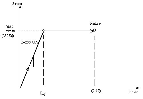 Modifications to the previous ANSYS model:
(1) Define and fill Bilinear Kinematic Hardening table (BKIN)
    Preprocessor - Material Props - Material Models - Structural
                 - Nonlinear - Inelastic - Kinematic Hardening - Bilinear
    Yld stress = 380E7 (in cm-g-s units)
    Tang Mod = 0.

    Material - Exit

(2) Change the magnitude of the pressure load:
    Solution - Loads/Delete - Pressure - On areas
    Pick the three areas at the bottom of hole - OK - OK

    Solution - Loads/Apply - Pressure - On areas
    Pick the three areas at the bottom of hole - Ok
    Value = 1.0e9
    OK

(3) Solution options:
    Solution - Analysis type/New analysis = Static - OK
    Solution - Sol'n Control
    Basic:  Analysis option = Large Displacement Static
            Time at end of load step = 1.0
            Automatic time stepping = on
            Number of Substeps = 10
            Maximum no of substeps = 10
            Frequency: Write every substep
    OK

(4) Solve / Current LS


(5) Take a look at the file called Lug.mntr

 SOLUTION HISTORY INFORMATION FOR JOB: Lug.mntr

 ANSYS RELEASE  5.7             .1      09:13:13    03/18/2002

 LOAD SUB-  NO.   NO.  TOTL   INCREMENT    TOTAL       VARIAB 1    VARIAB 2    VARIAB 3
 STEP STEP  ATTMP ITER ITER   TIME/LFACT   TIME/LFACT  MONITOR     MONITOR     MONITOR
                                                       CPU         MxDs        MxPl

   1     1    1     2     2   0.10000     0.10000      7.7900     -.83903E-02 0.78886E-30
   1     2    1     1     3   0.10000     0.20000      12.730     -.16780E-01 0.78886E-30
   1     3    1     1     4   0.15000     0.35000      17.410     -.29365E-01 0.78886E-30
   1     4    1     1     5   0.22500     0.57500      22.010     -.48241E-01 0.78886E-30
   1     5    1     4     9   0.21250     0.78750      33.880     -.71821E-01 0.18432E-02
   1     6    2     3    18   0.10000     0.88750      59.750     -.97588E-01 0.27577E-02
   1     7    1     4    22   0.56250E-01 0.94375      71.670     -.15595     0.66519E-02

You can also check List / Results / Load Step Summary.

This indicates that 7 load substeps are performed, CPU time for each that took for the solution
of  each substep, and the percentage of load that is applied (Total Time). Note that the
lug collapses after 94% of load is applied.

(6) You can look at results for each substep by
    General Postproc -
    By Load Step - Set LSTEP=1, SBSTEP = 1 to 7 to LAST.